


DIY PDF LINK HERE:
https://drive.google.com/file/d/1mnO...ew?usp=sharing
As mentioned, if you guys have any constructive criticism or questions or need any help, you can post your pics here and I will do my best to help however I can... There is some stuff I may have left off the DIY because I did it after the fact, below you will see my revisions/additions/edits as a living doc:
Rev - 10/1/22
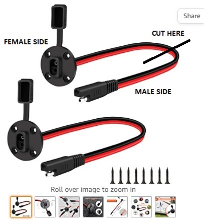
1. 12v power supply I was not clear with how I installed/ran power. Reference Image below. You will cut the line a the specified cut point, then strip off about 1/4in of the protective plastic sheath for each sides positive and negative wires to expose the copper line inside. When you cut the line in half the idea is that it creates a male plug and a female socket. The socket is mounted to and ran inside the box, and the plug is ran to the battery. Continue below:
- The female side (Inside the box*) will be the side that you will need to measure diameter, drill out and then install into the box. I had 4 short self tapping screws available to me that I just used a drill to drill into the box after I drilled out the hole for the wire to go through and the mount to sit flat on the box. This negative line will join with your 4 into 1 negative solenoid line and both will tap into position one on the RF Chip. The positive line is the line that you will need to put the small jumper on from the PDF, after you crimp on the jumper, this line will go to position 2 and the jumper will jump to position 4.
- The male side (ran from battery to box*), you will crimp into place your inline fuse on the positive (if you decide to run one, I recommend you do*), then you will crimp both the positive and negative lines to your battery lead lines (the lines that will literally attach to your battery*). The batter lead lines should be long enough to reach from the box to both the positive and negative terminals of your vehicle. You can make them different lengths if you would like as generally your box will sit on the passenger side of the vehicle, and the positive terminal is on the driver side, thus you can make the positive a little bit longer to reach the driver side. Versus a shorter negative line with the box and the negative terminal both on the passenger side.
2. I forgot to mention that the RF remote chip's "box/case" will probably need to be trimmed to accommodate all the wires. I just used some wire snips to do this, it does not need to be perfect or precise, just trimmed enough to allow all the lines to plug into their position with the cover on. Also, I forgot to explain, but the reason I "fold" the U shaped connectors in half is to create a small little prongs which can easily go into the RF Chip's terminals and fasten down tightly. If you follow my directions you will better understand the idea for this when you see and do this process in person.
REV - 10/3/2022
Couple small revisions/additions.
1. A MAJOR NOTE I FORGOT TO ADD WHICH APPLIES TO COMPLETE INSTALL - When using PTC (push-to-connect*) fittings, it is very important you do your best to cut ALL air tubing as square as possible. If you are careless and cut the tubing diagonal or at crazy angles this can possibly lead to leaks as the tubing will not be able to "seat" correctly in the fitting to create an air-tight seal. They do not have to be perfect, but as close to square as possible is your best bet. If you experience any leaks, you can use soapy water as usual to identify and solve.
2. I realized on my PDF that step #2's last sentence got cutoff by the picture. It should read - "Once all the solenoids are mounted in box and you confirm everything fits well and can all be snugged up, uninstall them as you will need them loose until later steps."
3. Step 3 - I should add that if your bulk heads are not "perfectly" matched up with your solenoids in either height or spacing placement, DON'T WORRY, the box will still work and function just fine. 4mm air tubing is extremely small and flexible so it can bend and flex to fit your setup. Just be sure to cut all your air tubing as square as possible as mentioned above. Gentle/soft bends are ok, but keep in mind that when installing any airlines, do your best to avoid any obvious obstructions or hard bends or kinks in the lines as these can hinder air flow as well.

 Reply With Quote

 ... Let us know here if you guys have or experience any challenges or have any input to add so that others can benefit in the future as well. And of course last but not least, pics of course of your box and rides once completed!


Bookmarks