Audizine - An Automotive Enthusiast Community

Page 1 of 3 123 LastLast
Results 1 to 40 of 105
  1. #1
    Senior Member Three Rings MongoMcG's Avatar
    Join Date
    Apr 15 2022
    AZ Member #
    691122
    My Garage
    B8 A4, C2 Corvette, Austin-Healey 3000 BJ8, SN95 Mustang, 36 Ford hot rod truck, A4 B9 S-line, A3 8V
    Location
    Michigan

    My metal mistress is having a mid-life crisis - mighty big K04 build thread

    Guest-only advertisement. Register or Log In now!
    This thread is in progress. I will be updating. Please note that I give part numbers, not links. But, if a vendor wants to pay me to insert links...

    The next stage of the build has begun after a long break, and this thread is being updated.
    Phase II - The Resurrection, begins at post #81

    Even after eleven and a half years, 28 tires, one TSB, two brake jobs, one trampoline, 14 oil changes, one already dead deer, one timing chain, three windshields, one daughter and a Jeep in the driveway, one wheel bearing, one battery, one very large bird, one small rodent, and 136,000 miles of a great driving experience - we love this car, my wife and I.


    What are we doing to the car, and why would you be interested? A turbo upgrade and supporting mods are literally and figuratively breathing new life into the car. An itemized list is below, but basically we are adding more air, more fuel and some suspension and handling upgrades. We are also pre-emptively replacing known failure points, scrubbing off 11 Michigan winters and changing all of the fluids. We are biting off a lot in one go, so we'll get plenty of information to chew on here. I will be adding tools, tips, and part numbers for just about everything we are doing including the part #'s and torque specs for bolts, and whether they are "one time use" and must be replaced. The factory build did well, so I am obsessively sticking with original torque specs.

    Although I am doing everything in one go it'll take a while, so this thread is broken down to smaller, more detailed posts. I note a few hiccups and surprises that are not covered in other threads & videos available online. Don't get me wrong; those posts and videos helped me a lot. I mean a lot a lot. So much so that I'll link to those posts I found most helpful at the appropriate spots in this thread.

    There is an awesome thread here for ebay/hybrid/big turbos and another for the 1070X where I am learning a lot.

    Tip: Look for links to the detail posts (within this thread) for each of these sections and for some of the line items. On some browser configs, if you are not logged in as an audizine.com member the links will bring you right back here, so I included the post numbers (upper right corner of each post) for manual navigation.


    Itemized list of what we're building
    First, for reference, here are the relevant codes for the car:
    Engine: CAEB (EA888 Gen 2), Gearbox: LRY (0B2), Rear Diff: 0AR (0BC) - this is the final drive for 2011 A4 2.0 with 6sp MT and some 2011 S4's with automatic transmission.


    Tuning

    Ward performance Tuning (WPT) is creating a custom tune for the car. In progress
    Here's a link to post #43 - Lessons learned while taking on an Audi project
    Here's a link to post #50 - Let the tuning begin - a guide for the tuning newcomer, by a newcomer


    Air Flow

    Upgrades and Keepers - from intake to exhaust
    • K&N cold air intake (69-9505T) - completed
      -Here's a link to post #12 - adding heat shield to K&N's heat shield
    • CTS Turbo 1070X K04 Hybrid turbocharger (1070X) - completed
      -Here's a link to post #13 - replacing the kinked vacuum lines on the turbo
      -Here's a link to post #31 - Bench prepping the turbo - transferring components, measuring the waste gate actuator pressures and distances
      -Here's a link to post #32 - More turbo bench prep - grinding the turbo for fitment
      -Here's a link to post #33 - Fitment issues continued
      -Here's a link to post #34 - Prepping the engine bay for a smooth, snag free turbo installation
      -Here's a link to post #37 - Turbo and turbo blanket installed
      -Here's a link to post #39 - Video - first start, second start and warm up
      -Here's a link to post #42 - Waste gate actuator and turbo blanket interference
      -Here's a link to post #43 - Reinstalling the turbo blanket so it doesn't interfere with the waste gate actuator arm
    • CTS Turbo turbocharger blanket for K03 & K04 (CTS-TB-B-03) - completed
      -Here's a link to post #43 - Reinstalling the turbo blanket so it doesn't interfere with the waste gate actuator arm
    • Wagner Tuning Competition front mount intercooler and silicone pipes (200001045KT) - completed, easy install, no detail post, but here's a tip: the stock IC and radiator setup has vertical plastic panels on either side of the radiator core support that keep air passing through the FMIC and radiator; they are important to the car's cooling system as they insure air passes though the FMIC/AC/radiator and not around them, so the plastic panels should be reinstalled after the new FMIC is installed. Trim the lower third of each to fit around the new FMIC inlet and outlet. The trimming of these pieces eliminates their lower mounting point, but the front bumper catches them and holds them in place pretty well.
    • CTS Turbo aluminum charge pipe (CTS-IT-267), with port for future water meth injection if needed - completed - easy install once the fender liner is out, no detail post
    • ECS silicone hose from charge pipe to T.B. with their stupid logo on it (017621ECS01A) - completed - easy install after trimming the throttle body end of silicone hose 1 13/16" and the charge pipe end of the hose 1 1/4" due to size increase over stock of the IE intake manifold
      -Here's a link to post #25 - IE IM install, part 6 of 6, bending the hard fuel line and wrapping up the driver side of the engine
    • Stock throttle body (original, 06F133062Q) - installed on new intake manifold - completed - easy install, no detail post
    • Integrated Engineering Intake Manifold - Black Velocity Stack Cover (IEIMVC1-bk) - completed
      -Here's a link to post #15 - IE IM install, part 1 of 6, component transfer
      -Here's a link to post #18 - IE IM install, part 2 of 6, making the bracket to mount the vac purge solenoid on the IE IM
      -Here's a link to post #20 - IE IM install, part 3 of 6, vacuum block-off and left over parts
      -Here's a link to post #16 - IE IM install, part 4 of 6, a home remedy solution to shrink the teflon seals onto the fuel injectors
      -Here's a link to post #24 - IE IM install, part 5 of 6, the IE intake manifold is going in the car
      -Here's a link to post #25 - IE IM install, part 6 of 6, bending the hard fuel line and wrapping up the driver side of the engine
    • Integrated Engineering hi-flow catalytic converter/down pipe and mid pipe (IEEXCG1) - completed - easy install, no detail post
    • Stock mid-muffler (original, 8K0253409) - stock factory install
    • Stock rear muffler (original, 8K0253609) - stock factory install

    To keep track of all this air we are installing the P3 V3 digital gauge (3P3AB8X) and P3 analogue boost sensor (P3ABS).
    Here's a link to post #29 - installing the P3 gauge and P3 boost sensor


    Fuel System

    Upgrades and Keepers
    • 034 Motorsports high pressure fuel pump piston upgrade kit (034-106-6052) - completed
      -Here's a link to post #6 - fuel pump removal, piston upgrade and re-install
    • Audi HPFP (stock, new, 06J127025L) - completed
    • All else original from factory - stock factory install
      -Here's a link to post #16 - a home remedy solution to shrink the teflon seals onto the fuel injectors
      -Here's a link to post #25 - IE IM install, part 6 of 6, bending the hard fuel line and wrapping up the driver side of the engine

    To keep an eye on air-fuel ratios and error codes we are installing the P3 V3 digital gauge (3P3AB8X).
    Here's a link to post #29 - installing the P3 gauge and P3 boost sensor


    Ignition

    Upgrades and Keepers
    • APR Upgraded Ignition Coils (MS100208-4KT) - completed - easy install, no detail post
    • Iridium Spark Plugs (BKR8EIXKT) - one heat range colder, gapped to .024" - completed - easy install with tool part #S-3858-125, no detail post
    • All else original from factory - stock factory install

    To keep an eye on ignition timing and error codes we are installing the P3 V3 digital gauge (3P3AB8X).
    Here's a link to post #29 - installing the P3 gauge and P3 boost sensor


    Carbon Build-Up Fix & Mitigation

    • Walnut blasting the intake ports - completed
      -Here's a link to post #4 - walnut shell blasting
    • ECS Performance baffled oil catch can system (turbo side of breather/PCV) (004136ECS01KT) - completed easy install, but see link for important info
      -This kit blocks off the breather to intake manifold port - this is a no-no
      -Here's a link to post #59 - Why and how I'm keeping the can and kicking the port blocker
      -Here's a link to post #65 - Opening the ECS Catch Can of Worms Increased My Oil Consumption


    Suspension & Subframe
    Upgrades - back to front
    Here's a link to post #7 - suspension and subframe upgrades install
    • 034 Motorsports rear diff carrier mount inserts (034-505-2016) - completed
    • 034 Motorsports rear diff mount insert (034-505-2019) - completed
    • CTS Turbo transmission mount insert (CTS-HW-0150) - completed
    • ECS Billet X-brace, to replace rusted but serviceable original (004802LA01AKT4) - completed
    • Canyon Run CR-15 front strut tower brace (CR-15) - completed
    • Audi lower radiator support braces to replace rusted but serviceable originals (8K0805527A and 8K0805528A) - completed
    • All else original from factory - stock factory install


    Preemptive Parts Replacement

    The While I'm In There stuff, replacing known failure points and a few other goodies. All are genuine Audi parts, unless noted
    • Vehicle battery - 520A (110Ah) (000915105DL) - completed - easy install except for coding the new battery via OBDeleven, no detail post
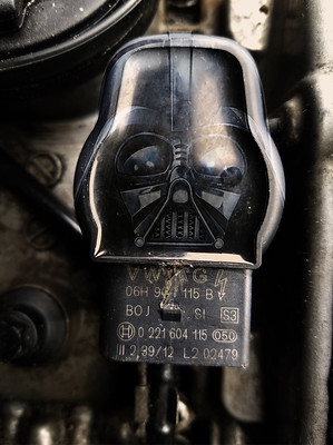
    • Diverter valve (06H145710D, but I used the Pierburg OEM version 7.01830.13.0) - completed - easy install, no detail post
    • Engine Oil Dipstick (06J115611L) - completed - easy install, no detail post
    • Pressure Control Valve (PCV, breather) Repair Kit contains PCV valve with gasket and 9 bolts (06H103495AKT3KT) - completed - easy install, no detail post
      -Note: My car had the oil consumption update per TSB#2027731r8, so this is version 06H103495AK of the PCV. Without the oil consumption update the PCV would be version AH. Also note the oil consumption update included a new front seal and a software upgrade.
    • Water pump (06H121026DR), Repair kit (06H121026BAKT) - completed
      -Here is a link to post #11 - installing the water pump
    • Vacuum pump gasket (06H103121J) - completed
      -Here's a link to post #21 - installing the vacuum pump gasket (aka vacuum pump seal)
    • Coolant line O-rings (4E0121666 38x4mm, and N90765301 32x4mm) - completed
      -Here's a link to post #19 - installing the coolant line O-rings
    • All splash shield/belly pan hardware - completed
    • Serpentine belt (06B903137D) - replacing with ECS Kevlar reinforced, because it's red - completed - easy install, no detail post
    • N75 waste gate frequency control valve (06F906283F) because the CTS Turbo 1070X K04 hybrid has a no name thing on it made from chinesium - completed - easy install while the turbo is out of the car. No detail post, but...
      -Here's a link to post #13 - fixing the kinked vacuum lines on the turbo


    Fluids

    Audi Genuine, Aftermarket and Additives Used
    Here's a link to post #10 - all fluids
    • Engine oil - Liqui Moly Leichtlauf High Tech Engine Oil 5w-40 (2332) - First try, used Castrol until now - Torque new (required) drain plug to 30Nm - completed
    • Engine oil additive - Liqui Moly Cera Tec 300 mL (20002) - Same or similar to my dealership service - added every time - completed
    • Engine oil additive - Liqui Moly Motor Oil Saver 300 mL (2020) - First try. We'll see if we like/hate it. - completed
    • Engine oil filter - Hengst oil filter (Hengst# H14W30, Audi# 06J115403Q) - hand tighten - completed
    • Gearbox oil (G055532A2) - Torque drain and fill plugs to 45Nm - completed
    • Gearbox oil additive - Liqui Moly MoS2 anti friction additive (2019) - completed
    • Rear differential gear oil - 75w90 (G052145S2) - Torque drain and fill plugs to 45Nm - completed - completed
    • Rear differential gear oil additive - Liqui Moly MoS2 anti friction additive (2019) - completed
    • Coolant - Vaico G13 (Audi# G013A8J1G, Vaico# VA-013) Flushing the G12 - completed
    • Coolant additive - Red Line Water Wetter (80204) - completed
    • DOT4 brake fluid (B0007501LDSP) - completed
    • Power steering fluid - CHF 202 (CHF202) - completed
    • Power steering fluid additive - RVS triboceramic (P2RVS) First try. Will not add if testing of the new fluid satisfies - completed
    • Turbocharger additive - Liqui Moly Pro-Line turbocharger additive (22074) One time for the new turbo or whenever the turbo is removed and reinstalled - read the detail post for the Fluids section to find out why - completed


    Yet to be sourced or determined
    Stuff I am still looking at (will edit here when decisions are made)
    • Clutch - maybe the South Bend Stage 2 with dual mass flywheel. I have not yet found the shop to do the work.
    • Rear main seal - the 034 Motorsports version or that other one that's available.

    Stuff we'll do if/when it's forced upon us
    • Rods & Pistons - leaning toward IE forged rods and Mahle pistons
    • Front Upper Control arms - those bushes have to crap out at some point
    • Other suspension bushings and ball joints
    • Engine mounts - 034 Motorsports Street/Track density


    Tip: Pics used throughout this build thread and more can be viewed full size at my Flickr album page. There are a lot of disassembly photos that are not used in this thread that will be most helpful for re-assembly of components.https://flic.kr/s/aHBqjzZ3nv

    Disclaimer: This thread is solely intended to illustrate the parts and procedures I used while working on my car. I make no guarantee of the correctness of the parts and procedures for any other car or for the safety of persons working on any car. I put in a lot of research, but still, use this information at your own risk. I'm just a classic car and hotrod guy who decided to work on my sedan and share what I found.


    The next stage of the build has begun after a long break, and this thread is being updated.
    Phase II - The Resurrection, begins at post #81
    Last edited by MongoMcG; 04-09-2024 at 10:14 PM. Reason: Formatting
    “The Force is strong with this one.”
    My K04X build thread

  2. #2
    Veteran Member Four Rings 19birel's Avatar
    Join Date
    May 10 2015
    AZ Member #
    332119
    My Garage
    '13 A4 Prem+, '00 VW Golf, '21 VW GTI
    Location
    Pittsburgh PA

    You're going all out, thats awesome!

    For the tune, Tyler, who goes by Ward Performance Tuning, and hook you up with a strong custom tune for the 1070x. He's the only one really doing custom tunes around here, I think his username is Tylerjdubbs, you can find some his posts in the 1/4mile thread to message him.

    As for the clutch, a lot of guys have been having issues with Southbend products lately, so I'd be inclined to stay away. I got a Spec Stage 3+ and am very pleased with it, and the OEM-like drivability. I also opted for an ECS lightweight flywheel, which I love. No added NVH and rev matching is much nicer. Takes a little getting used to but I'm a fan.
    "Emmaline" Monsoon Grey/Titanium Grey 2013 A4 Prem+ 6MT w/Sport Pkg BUILD THREAD
    S-Line converted | A7 356mm BBK | OEM 19x9" A8 wheels | Spec Stage 3+ Clutch | ECS LWFW | IE 3" downpipe | CTS catback | IEStage2+JB4 Stack Tuned | Meth Injection and more...
    Previous Audi: "Adeline" 1999.5 B5 A4 1.8TQMS

  3. #3
    Senior Member Three Rings MongoMcG's Avatar
    Join Date
    Apr 15 2022
    AZ Member #
    691122
    My Garage
    B8 A4, C2 Corvette, Austin-Healey 3000 BJ8, SN95 Mustang, 36 Ford hot rod truck, A4 B9 S-line, A3 8V
    Location
    Michigan

    Thanks! I'll be looking up Tyler right away.
    “The Force is strong with this one.”
    My K04X build thread

  4. #4
    Senior Member Three Rings MongoMcG's Avatar
    Join Date
    Apr 15 2022
    AZ Member #
    691122
    My Garage
    B8 A4, C2 Corvette, Austin-Healey 3000 BJ8, SN95 Mustang, 36 Ford hot rod truck, A4 B9 S-line, A3 8V
    Location
    Michigan

    Walnut blasting detail post

    Walnut Blasting Results and Tips

    Tools:
    The blaster kit:
    • Walnut shells 18/40 blast media - 50 pounds (B1100050)
    • 034 Motorsports Audi & VW direct injection head port cleaning tool (034-108-Z054)
    • Walnut Blaster Nozzle (B1100009)
    • Harbor Freight 20 lb. abrasive blaster (98030)
      - This is pretty much everything sold in the $300 kits from our favorite suppliers, for $245. If not for the 30 bucks to ship the walnut shells this would have been a significant savings. I would find a local source if this was the only thing I had going on.

    Other tools:
    • Safety glasses
    • Air compressor
    • Shop-vac with 1-1/2" hose
    • Straight and double bend hose picks (long, fine point, not the fat ones - I use Milwaukee pick set 48-22-9215)


    Tip: Pics used throughout this build thread and more can be viewed full size at my Flickr album page. There are a lot of disassembly photos that are not used in this thread that will be most helpful for re-assembly of components. Sorted by order of work, so there may be some jumping around. https://flic.kr/s/aHBqjzZ3nv

    The set up:
    • I used Shop-vac model 87L650C. It's a beastly 16 gallon 6.5 peak HP heavy duty vacuum capable of 210cfm and 60 inches of sealed pressure - more than enough for this job, but I appreciated the high suck factor.
    • I snagged a 1-1/2" hose from the dust collector in the woodshop. It has a 2-1/2" end to fit in the Shop-vac port.
    • I wasn't sure how long 50 pounds of walnut shells would last, so I started with 5 pound loads in the blaster tank - more on this later.
    • In my case, I have a lot taken off of the car for the rest of the build project, e.g. oil filter, water pump and heater hoses, so there are a lot of exposed ports, hose ends and electrical connectors that I covered with blue masking tape. I also covered the alternator and the three intake ports that I was not working on at the moment.


    I'm glad I did, because...
    (Gotcha) The first time I opened the valve at the business end of the blaster hose, the kickback popped the nozzle out of the intake cleaning tool and sprayed walnut shells which bounced and flew all over the place. One hand is holding the vacuum hose and the other hand is opening the valve and trying to hold onto the blaster wand at the same time. Same for closing the valve. So figure that out before you start.

    • I used the media blasting kit paired with my trusty old 1997 Campbell Hausfeld "Farmhand Cast Iron" 2HP (4.5HP peak) 20 Gallon air compressor. The rating for this compressor is a measly 5.5 cfm, but the workflow for this gig is a lot of start/stop action so the cfm doesn't matter. I have a 40 micron filter at the air compressor tank output.


    • Air compressor output set to 80psi, fed through 50 feet of high quality 3/8" air hose with a 1/4" quick connect (female) at the end
    • To keep the blaster tank nice and dry, a cheapo' Harbor Freight disposable inline moisture filter (63951) is plumber's taped and screwed into the blaster tank's air input. The other side of the moisture filter has a 1/4" quick connect (m) plumber's taped and installed for the air hose connection.


    Steps
    • Make sure all blaster tank valves are closed
    • Make sure engine valves are closed. You will have one port's valves open, even slightly, so tape over that one and save it for last because you'll need to turn the engine by hand using a 24mm socket and breaker bar on the crankshaft pulley bolt - turning clockwise only(!) as you are looking at the pulley from the front of the car.
    • Load desired amount of walnut shells in blaster tank
    • Connect the compressor hose to the blaster tank with 1/4" quick connect
    • Charge the blaster tank (top valve)
    • Open valve on interconnect hose to bottom hose fixture
    • Double check that the valve at the business end of the blaster hose is closed, then open the bottom valve on the blaster tank to charge the blaster hose
    • Fire up the Shop-vac (with intake cleaning tool attached) and place intake cleaning tool over an intake port so the blasting wand enters the left or right side of the intake port. We will flip it and do a second blast for best coverage.
    • Insert wand into port cleaning tool. I liked feeling for the valve stem and tucking the blast wand deep to one side of it.
    • Now, about that 5 pounds of walnut shells: I figured I can hit each port with two loads, 8 loads total, and have 2 pounds left for any final touchups. I would use a pick to remove stubborn stuff between blasts. My first blast was that disastrous blow out which went on for about a 3 count. But the first successful blast I gave a 10 count in my head and moved the wand around very quickly. I had about half of the shells left in the blast tank, so I flipped the intake cleaning tool and gave another 10 second blast with fast wand movement. That emptied the blaster tank. Note: when I did the second intake port I discovered a slower wand movement works better. You have enough angle to play with to reach the other valve in the same port.
    • Between blasts I used a straight pick and the pick with the double bend to scrape away the really stubborn stuff - it was like somebody welded pencil lead onto the valves. But I also used the picks to clean the back sides of the valve which the blaster cannot reach, and especially to clean out the shocking amount of crud that was stuck around and behind the valve guides.
    • Port 1 was definitely the toughest, and 4 was the easiest (surprising because port 4 had the most amount of build-up). I spent 10-15 minutes scraping each port. It became obvious that I was being far too conservative on my shell usage and I was going to end up with 20 pounds worth of walnut shells taking up space in my garage, so less scraping, longer blasting - yay - concentrating on full coverage but giving extra blast time to the top surface of the valve (the wide part). The stems and the port walls cleaned up easily, but this wide part of the valve (and the curved transition to the stem) is where the baked on stuff was really sticking.
    • By the time I got to port three I discovered my best practices: cover port; insert nozzle (deep to outside edge of valve); pull nozzle back toward you while turning it 180° for a five count; push in to other side of same valve while turning the nozzle back 180° for a five count; shut off valve; remove nozzle; flip the intake port cleaning tool and vacuum hose 180° so the nozzle enters the other side of the port and repeat the wand action; close valve; move the intake port cleaning tool to the side; scrape with picks; a final touch up blast of 5-10 seconds on the valve tops.
    • Use a crevice tool on the Shop-vac to suck out as much debris as possible, then use compressed air to blow out what's left.

    That's it. It took about 2 hours from first blast to clean up. And here are the before and after shots - sorry about the shadows in the before shots:
    Port 1:


    Port 2: (note the valves are open in the before shot)


    Port 3:


    Port 4:


    Helpful Links:
    None for the blasting, but here is one for removing the intake manifold (intake removal starts at 3:17 minutes)
    Last edited by MongoMcG; 07-21-2022 at 11:29 PM. Reason: Added link to photo album
    “The Force is strong with this one.”
    My K04X build thread

  5. #5
    Senior Member Three Rings MongoMcG's Avatar
    Join Date
    Apr 15 2022
    AZ Member #
    691122
    My Garage
    B8 A4, C2 Corvette, Austin-Healey 3000 BJ8, SN95 Mustang, 36 Ford hot rod truck, A4 B9 S-line, A3 8V
    Location
    Michigan

    About that trampoline...

    About that trampoline mentioned in the original post...
    We had a movable basketball net in the driveway that liked to blow over in a windstorm (we get strong winds in our neighborhood - a bonus feature from the ridges and valleys cut into the landscape by glaciers a while back). The winds were enough of a concern for me to tie town the trampoline in the back yard with two screw in stakes (for big dogs).

    Eight weeks after taking delivery of our car a mighty wind and thunderstorm started raging. I knew the younger daughter's car was parked under the basketball net, so I started down the stairs to go outside and lay the net down and pull my car into the garage. On my way down the stairs my daughter called out, "Dad!" and then I heard a crash sound. I said, "Dag nabbit, I was just going out to move the net." She said, "It's not the net. The trampoline just flew by my [upstairs] bedroom window. I rushed out of the garage to discover the basketball net was still standing but the trampoline was laying upside down on top of my car. That means the trampoline sailed 60 feet through the air at a height of at least 12 feet, over the basketball net and over my daughter's SUV to find it's intended target - our 8 week old car.

    This was a big oval trampoline with a massive steel frame. One of the poles that hold the net around the perimeter of the thing decided to insert itself between the hood and the headlight of the car and crank it open like an old fashioned can opener, and the frame went crashing through the back window and through the package shelf. The thunderstorm was heavy, so a lot of water entered the interior and trunk of the car though the gaping damage. It fried the B&O sound system. But the damage was everywhere, from scratches to dents. They replaced and/or painted every panel except the passenger rear door. The cats at Cox Collision in Brighton did an amazing job and stand behind their work. The clear coat on the hood lifted in a couple of small spots a year later, so I took it back to Cox Collision; they fixed everything up, and didn't charge me a dime (they went after PPG for payment).


    “The Force is strong with this one.”
    My K04X build thread

  6. #6
    Senior Member Three Rings MongoMcG's Avatar
    Join Date
    Apr 15 2022
    AZ Member #
    691122
    My Garage
    B8 A4, C2 Corvette, Austin-Healey 3000 BJ8, SN95 Mustang, 36 Ford hot rod truck, A4 B9 S-line, A3 8V
    Location
    Michigan

    High pressure fuel pump upgrade detail post

    High pressure fuel pump upgrade install
    Tools:
    • Safety glasses
    • Hose clamp pliers (I use linesman pliers all the time without issue)
    • M10 triple square socket (OTC 5942 8-Piece XZN 'Super Short' Triple Square Socket Bit Set) with a long extension, ratchet
      - I have regular and long sockets as well, but I use these stubbys all the time, and they are a must if you are removing the turbocharger coolant line that is right next to the car's frame.
    • 17mm open end wrench
    • Torque wrench set to 20 Nm for installation - none of the video guys torqued to spec, but my OCD won't let me do that.

    Specialty tools:
    • Audi 2.0TFuel Pump Install Tool For the 2.0T - a must (10.127.101TK)


    Parts:
    • 034 Motorsports High Pressure Fuel Pump Piston Upgrade (034-106-6052)
    • Audi High Pressure Fuel Pump (if you break the old one) (06J127025L)
    • Bolts: 2x N10572403 M8x16 Pan-head (triple square) bolts, torque to yield, replace with new bolts
      -Hand tighten, then one full turn each until pump flange contacts the vacuum pump, then torque to 20Nm each - incremental steps, turning each bolt in turn about a quarter turn.
    • High pressure fuel pump O-ring (WHT005184) - should be replaced every time you pull the fuel pump

    Tips and Tricks:
    • Be mindful of the fuel pressure sensor on the HPFP when you have it in the vise
    • Lubricate and be gentle when installing the upper piston guide (the part with a seal) over the new piston. The piston has a shoulder where the spring retaining clip goes, and the seal meets a little resistance there. Slight pressure with both thumbs to keep everything straight will pop the seal over the shoulder without tearing it.
    • I could not find a torque spec for the big nut that holds the piston guide in place (the piece that the specialty tool cranks on). I torqued to 65Nm, but now wish I did as much as 90Nm.
    • You may need to crank the engine by hand to get the thing on the cam that pushes on the cam follower to a flat spot. I think it has 4 sides, and if one of the corners is anywhere in the "push on the cam follower" range you will have a hard time getting the fuel pump installed past the O-ring before hand tightening the bolts.
    • Be mindful of the O-ring upon installation.

    Helpful links:
    Upgraded piston installation:
    https://store.034motorsport.com/docs...structions.pdf

    Fuel pump removal/installation:


    This guy needed a 16mm wrench for his fuel line fitting, but the 2011 B8 is a 17mm fitting.


    Also this one for fast work (fuel pump removal/installation begins at 5:15 minutes).


    Or if you really want detailed step by step, including removing the fuel pump fuse, you have to put up with this guy.

    Other useful information:
    Torque specs for the Fuel injection system:


    From the Audi service manual:

    1 - Quick-Release Coupling with stop valve - no replacement part; included in item 11
    2 - Connector
    3 - Fuel Pressure Regulator Valve or Fuel Metering Valve - Different versions depending on the manufacture of the high pressure pump:
    ♦ Fuel Pressure Regulator Valve -N276- or
    ♦ Fuel Metering Valve - N290- Integrated in the high pressure pump, cannot be replaced separately
    4 - High Pressure Pump - Do not bend when installing
    5 - O-Ring - Replace after removing, coat with engine oil
    6 - Roller Tappet - Remains inserted in the vacuum pump after removing the high pressure pump
    7 - Vacuum Pump
    8 - Connection
    ❑ 40 Nm
    ❑ Replace every time it is loosened
    ❑ For the high pressure pipe
    ❑ Counterhold when loosening the union nuts
    9 - High Pressure Pipe
    ❑ Tighten the union nut to 27 Nm
    ❑ Do not change the bending shape.
    ❑ Do not install when under stress
    ❑ Coat the thread on the union nut with clean engine oil.
    10 - Bolt - M6 replace after removal (OP's edit: my 2011 B8 uses M8x16mm bolts)
    11 - Fuel Supply Hose from the fuel tank
    12 - Spring Clamp - Replace after removing
    13 - Spring Clamp - No replacement part; included in item 11
    Last edited by MongoMcG; 06-25-2022 at 11:27 PM. Reason: Added fuel pump O-ring part info
    “The Force is strong with this one.”
    My K04X build thread

  7. #7
    Senior Member Three Rings MongoMcG's Avatar
    Join Date
    Apr 15 2022
    AZ Member #
    691122
    My Garage
    B8 A4, C2 Corvette, Austin-Healey 3000 BJ8, SN95 Mustang, 36 Ford hot rod truck, A4 B9 S-line, A3 8V
    Location
    Michigan

    Suspension and subframe components detail post

    Suspension and subframe components install
    (I include part #'s, not links. I'm not selling for anybody.)

    Sections Below:
    • Overview
    • 034 Motorsports rear diff carrier mount inserts (034-505-2016)
    • 034 Motorsports rear diff mount insert (034-505-2019)
    • CTS Turbo transmission mount insert (CTS-HW-0150)
    • ECS Billet X-brace (004802LA01AKT2)
    • Canyon Run CR-15 front strut tower brace (CR-15)
    • Audi lower radiator support braces (core support to engine cradle) (8K0805527A and 8K0805528A)

    Overview
    These bolts-ons are very easy (with the right supplier). However, all but the radiator support braces require new bolts according to Audi specifications, and they are not included (except for the CR-15 strut tower kit which includes nuts and washers). The radiator support braces will still get new hardware because I am replacing all of the clip nut/screw combos I run across anyway. The clip nuts seem to be more prone to rust than most parts on this car.

    The front strut tower brace and the billet X-brace will increase steering responsiveness and reduce (or distribute) torsional forces, and that holds more optimal suspension geometry and tire contact in hard turns - at least up front. The other upgrades are designed to reduce the drivetrain slop designed into the car by Audi engineers. I like the rear to be a little looser than the front, but if the back end is too unpredictable I will add the 034 Motorsports rear subframe inserts and sway bar end links to reduce rear end slop.

    Tools for all jobs in this post:
    • Safety glasses
    • Jack
    • Jack stands x4
    • Mechanics creeper if you're over 50

    Tips and tricks:
    I swapped out my manual transmission oil while the x-brace was out because one can actually get decent access to the transmission drain plug.

    034 Motorsports rear diff carrier mount inserts (034-505-2016)
    Tools:
    • Breaker bar
    • 18mm socket
    • Ratchet
    • Torque wrench set to 55Nm for install
    • Jack (to support rear diff)
    • Silicone lubricant (I actually used Boeshield T9 - my go-to stuff. It's also a decent corrosion protection coating when it dries. I also like Tri-Flow lubricant)

    Parts:
    • 034Motorsport B8 Audi Rear Differential Carrier Mount Insert Kit (034-505-2016)
    • Bolts: 2x N10640501 M12x1.5x80 hex-head bolts (not in kit), must be replaced according to Audi, torque to 55Nm

    Helpful Links:
    https://store.034motorsport.com/docs...structions.pdf

    034 Motorsports rear diff mount insert (034-505-2019)
    Tools:
    • Breaker bar or impact wrench (I use the Milwaukee Fuel 2767-21B)
    • 16mm socket or impact socket
    • Torque wrench set to 55Nm for install
    • Jack to lift rear diff off of its front mounting point enough to slide in the new insert

    Tips:
    To get enough clearance to install the upper insert I had to lift the rear differential using the driveshaft joint as the jack point. I used a 10" chunk of 4x4 to fit between the rear seat footwells to make contact since the jack doesn't fit in there.
    Parts:
    • 034 Motorsports rear diff mount insert (034-505-2019)
    • Bolt: 1x N10719201 M10x95 hex-head and triple square bolt (not in kit), must be replaced according to Audi, Torque to 55Nm

    Helpful Links:
    https://store.034motorsport.com/docs...structions.pdf

    CTS Turbo transmission mount insert (CTS-HW-0150)
    Tools:
    • Breaker bar or impact wrench
    • M10 triple square socket or impact socket
    • Ratchet
    • Torque wrench set to 20Nm for installation

    Parts:
    • CTS Turbo B8 Audi Transmission Mount Insert (CTS-HW-0150)
    • Bolts: 2x N10724701 M8x60 pan-head (triple square) bolts (not in kit), must be replaced according to Audi, torque to 20Nm

    Helpful Links:
    I'm linking to the nice folks at 034 Motorsports installation guide for their product, which I'm sure is amazing. The steps are extremely easy and the same.
    https://store.034motorsport.com/docs...structions.pdf

    ECS Billet X-brace (004802LA01AKT2)
    Tools:
    • Breaker bar or impact wrench
    • 18mm socket or impact socket
    • Jack (optional) - I used it to hold up the X-brace for the first install. Did not use it for the second install and it was pretty easy.
    • Torque wrench set to 90Nm for installation (torque spec is actually 90Nm plus 135° turn)

    Parts:
    • ECS X-brace (004802LA01AKT2)
    • Bolts: 6x N91151101 M12x1.5x42 hex-head bolts.
    • Note (more of a rant, actually): bolts included in the ECS branded kit are 45mm instead of the stock 42mm, but fitment seemed okay. I was not certain because the four outer corner bolts felt like they were bottoming out instead of stretching to torque spec. My overactive brain thought there might be some drivability or even safety issues, so I emailed ECS with questions. That email was completely ignored. So was a reminder. I was asking for either assurance that their product was okay or to send the correct bolts. After being ignored for several days I went ahead and ordered the correct bolts for the pre face-lift cars. As it turns out, the 45mm bolts were probably fine and I spent 21 bucks for nothing except some bonus time under the car to re-do the install. ECS moves a lot of product, but so far I find ECS's tech support to be absolute garbage, a waste of time, and totally useless (unless you like being ignored). Is it too much to ask a company to stand behind their product? ECS turned a good customer into an angry customer.

    Helpful Links:
    http://bd8ba3c866c8cbc330ab-7b26c6f3...stallation.pdf

    Tip
    Swap out high mileage manual transmission oil while the x-brace is out because one can actually get decent access to the transmission drain plug.

    Canyon Run CR-15 front strut tower brace (CR-15) - waiting for car to stand on its own four feet instead of the jack stands
    Tools:
    • 13mm socket, ratchet, 4 inch extension
    • Flat head screwdriver
    • Torque wrench set to 20Nm for installation

    Parts:
    • Canyon Run CR-15 front strut tower brace (CR-15)
    • Nuts: 4x M8 13mm hex-head lock nuts (included in kit) - torque to 20Nm
    • Washers: 4x M8 washers (included in kit)

    Helpful Links:


    Audi lower radiator support braces (8K0805527A and 8K0805528A)
    [I]Tools:/I]
    • 13mm socket
    • Ratchet (short wobble extension may be needed)
    • T-30 Torx driver or socket
    • Torque wrench, small, set to 1.5 Nm for installation of torx screws
    • Torque wrench set to 23Nm for installation of M8 13mm hex nuts

    Parts:
    • Bracket for a radiator support (left) (8K0805527A)
    • Bracket for a radiator support (right) (8K0805528A)
    • Nuts: 2x (1 ea) N9076110 M8 13mm hex nut, torque to 23Nm
    • Screws: 2x (1 ea.) N10535502 T-30 torx screw, torque to 1.5Nm
    • Clip nuts: 2x (1 ea.) N90342504 (aka spring nut)

    Helpful Links:
    You really should not need any help with this one. But if you're wondering where these radiator support braces, or radiator support brackets, are, they sit very close to the radiator splash shield (belly pan) at the bottom-front of the car. They connect the engine carrier subframe and the radiator core support. This job is is simply remove and install with optional new hardware, torque to spec.
    Last edited by MongoMcG; 06-23-2022 at 07:58 PM.
    “The Force is strong with this one.”
    My K04X build thread

  8. #8
    Senior Member Three Rings MongoMcG's Avatar
    Join Date
    Apr 15 2022
    AZ Member #
    691122
    My Garage
    B8 A4, C2 Corvette, Austin-Healey 3000 BJ8, SN95 Mustang, 36 Ford hot rod truck, A4 B9 S-line, A3 8V
    Location
    Michigan

    Here's a factoid I learned recently - do not use brass brushes on aluminum if the part needs to deal with salt water (like road salt or coastal regions). Little bits of brass get embedded in the aluminum and salt water causes the two metals to react and dissolve the aluminum. Use a stainless steel scratch brush instead.
    Last edited by MongoMcG; 06-11-2022 at 11:23 AM.
    “The Force is strong with this one.”
    My K04X build thread

  9. #9
    Senior Member Three Rings MongoMcG's Avatar
    Join Date
    Apr 15 2022
    AZ Member #
    691122
    My Garage
    B8 A4, C2 Corvette, Austin-Healey 3000 BJ8, SN95 Mustang, 36 Ford hot rod truck, A4 B9 S-line, A3 8V
    Location
    Michigan

    History of the car - boring, but has info about the Titanium Sport Package

    This car has been perfectly lady-like. Well, until P0299 entered our lives. The K03's prognosis? She's dead, Jim, due to chronic, uncontrolled air diarrhea from a worn out wastegate. This single component failure put stuff in my head that probably shouldn't be there, and now the car is up on jack stands, the front bumper is off, the fender liners are out, and both sides of the engine are empty and look sad.


    We ordered it exactly how we wanted it in late 2010 with a wonderful sales person (Hi Slava) and waited months for delivery in February, 2011 - a Phantom Black on black 2011 Audi A4 B8, 2.0L TFSI Quattro, 6 speed manual gear box, Prestige with Titanium Sport package, MMI + Nav, and Bang & Olufsen sound. Inside, the sport package provides a three-spoke sport steering wheel, sport leather seats, black piano lacquer interior trim, and perhaps my favorite sport package feature, the black headliner; the cockpit takes you to a different place. Outside, the package blacks out the trim around the windows and grill and pops the backside with chrome tips. And it all rides on 19" titanium alloys - the perfect wheel for this car, just not in Michigan winters. The sport package suspension is what feels so good on the butt cheeks when driving maximally. It uses stiffer springs that drop the car about an inch (0.9") and uses the S4/S-Line front and rear sway bars.


    We got 93,000 miles out of the original brakes (my wife loves engine braking). We did the timing chain at 117,000 miles - it wasn't quite needed yet, but really, how far can you push it? (I think her engine braking reversed the stretch or wound back time or something). I just changed the original 11-1/2 year old battery and did the second brake job. The car was dealer serviced at every interval and has not experienced any major mechanical or component failure, knock on wood, except the t.c., wheel bearing and a few bumps, bruises and skirmishes with wildlife. There was an attempt to fix moderate oil consumption issues at 83,000 miles (PCV breather valve update, new front main seal and an ecu update, per TSB 2027731r8).

    Here's a link to that TSB, BTW:
    https://www.dropbox.com/s/sqmg3do3cd...02011.pdf?dl=0

    If you are wondering about the source of this and other files I will be posting here, I downloaded a lot of Factory Service Manuals, TSB's, Reference Books and more directly from the Audi Literature Website with a one-day subscription, https://literature.audiusa.com and I will be sharing pertinent information from them using a free Dropbox account and a free Flickr account I use for car forums. I highly recommend doing the one day subscription thing even if you are only going to tinker on your car.
    Last edited by MongoMcG; 01-24-2023 at 06:25 PM.
    “The Force is strong with this one.”
    My K04X build thread

  10. #10
    Senior Member Three Rings MongoMcG's Avatar
    Join Date
    Apr 15 2022
    AZ Member #
    691122
    My Garage
    B8 A4, C2 Corvette, Austin-Healey 3000 BJ8, SN95 Mustang, 36 Ford hot rod truck, A4 B9 S-line, A3 8V
    Location
    Michigan

    Fluids detail post

    Fluids

    Tip: Did you know? from the Audi service manual...
    2.26.2 Information for Engines with Turbochargers
    Pay attention to the following after starting the engine for the first time after changing the engine oil and oil filter:
    ♦ As long as the oil pressure indicator lamp in the instrument cluster is on, the engine may only run in idle.
    ♦ Do not touch the accelerator pedal!
    ♦ The indicator lamp goes out after the full oil pressure is reached and now the accelerator pedal can be pushed.
    Caution: Bumping the accelerator pedal can damage the turbocharger or destroy it completely. If there is insufficient oil, the bearings in the turbocharger can burn out after a few seconds because the turbocharge runs at a high speed. Turn off the engine right away if turbocharger leaks oil, vibrates or makes unusual noises.

    Fluid capacities - for Engine: CAEB (EA888 Gen 2), Gearbox: LRY (0B2), Rear Diff: OAR (OBC)
    *Disclaimer: For the 2011 A4 2.0TFSI Quattro 6sp MT sedan only. Other models may vary. Oil and fluid part numbers are for reference only. Always check with your Parts Department for the latest part information.
    • Engine Oil: 4.6L -- oil specification VW 502 00*. Use synthetic oil SAE 5W-40, 5W-30 or 0W-40. Refer to Technical Bulletin 2010043 for engine oils that meet this Audi standard.
    • 6sp manual trans: 4.8L -- oil part# G055532A2
    • Final drive (rear diff) 0BC: 0.9L -- oil part# G052145S2
    • Cooling system: 7.0L -- specification G 12 plus plus, coolant part# G012A8G*. (OP note: It is fine to flush and fill with G13.)
    • Power steering: 1.0L approximately, fluid part# G002000* or G004000*
    • Brake system: 1.0L approximately, specification FMVSS 116 DOT 4 or SAE J 1703, fluid part# B000750*
    • A/C system:
      -Refrigerant - Use only R134a, capacity 600g ± 20g (21.1 ± 0.7 oz.)
      -Refrigerant oil - Use a PAG oil with R134a, oil capacity (for Denso) 150 cc +/- 10 cc, part# G052300A2*
    • Windshield & headlight fluid: 4.5L, fluid part# G052164*


    Sections:
    • Overview
    • Engine oil and additives
    • Gearbox oil and additives
    • Rear differential gear oil and additive
    • Coolant and additive
    • DOT4 brake fluid
    • Power steering fluid and additive
    • Turbocharger additive


    Overview
    What is running through the veins and arteries of your car? Other than scheduled oil changes, two brake jobs and windshield washer fluid, my car had the stuff put in by the factory more than 11 years and 136,000 miles ago. When it comes to engine oil, there are as many opinions as there are brands, and there a a bunch of web sites dedicated to testing and arguing about oil. For engine oil and all the other fluids, the main factor for me was whether the stuff was Audi certified because their engineers are way smarter than me when it comes to fluids. For the additives it's hard to cut through the marketing hype and find real science. One is left with scant technical data and user's opinions when deciding if (and which) additives should be used. This user gave up research and went with a single brand for most of the additives - Liqui Moly (because it's made in Germany! lol).

    My gearbox oil was dark brown and thin, and I found very few metal shavings - virtually none in the oil and the drain plug had only about 6 small and less than paper thing metal shavings. The differential oil was still looking pretty good and zero shavings - probably could have skipped the rear diff.

    Part numbers are Audi, unless specified otherwise.

    Engine oil and additives
    Tools
    • Oil filter wrench of choice - specialty oil filter tool (Schwaben FC-04), or oil filter pliers (Tekton 5866), or channel locks, or a screwdriver punched through the oil filter, whatever)
    • Fluid extractor (Schwaben 6 Liter Fluid Extractor/Filler System - 007221SCH01A, with dipstick tubes (013810SCH01A) Note: I was swapping the drain plug for the oil pan so I did it the old fashioned way this time. See below for tips from the Audi service manual about using a fluid extractor to drain the oil.
    • Socket and ratchet if you are doing the drain plug
    • Torque wrench set to 30Nm for drain plug installation if you are doing the drain plug
    • Oil catch pan of choice
    • Funnel and container for old engine oil recycling (I use the empty 2-1/2 gallon water jugs we get at the grocery store)

    Parts
    • Engine oil - Liqui Moly Leichtlauf High Tech Engine Oil 5w-40, part#2332, 4 liters (we are also adding 0.6L of additives)
    • Engine oil additives - Liqui Moly Oil Saver (2020) and Ceratec (20002), 300mL each - my first try for the oil saver product to see if it helps with oil consumption
    • Engine oil filter - Audi 06J115403Q, Mann 06J115403C, or Hengst 06J115403Q - no torque spec found, lubricate seal with clean oil and hand tighten
    • New magnetic SS drain plug and new (required) crush washer - Votex DP001 M14x1.5 w/ neodymium magnet - Torque to 30Nm

    Helpful Links
    • none

    Tips:
    Using the 2 additives (which are 300mL each) results in needing only 4 liters of new oil to make a correct total of 4.6 liters.

    If you are using the oil extractor here is info from the Audi service manual...
    – Insert the extractor into the oil dipstick tube or the oil filter housing and extract the engine oil.
    ♦ Use a flexible extractor with the largest possible diameter.
    ♦ Insert the extractor only until the first resistance is felt. Otherwise the tip will bend when it touches the bottom of the oil pan and a lot of old engine oil will remain inside the engine.
    ♦ Always read the Operating Instructions that come with the extracting device.

    Gearbox oil and additives
    Tools
    • Breaker bar and ratchet
    • 10MM Hex socket
    • Oil transfer pump
    • Torque wrench set to 45Nm for drain and fill plug installation
    • Oil catch pan of choice
    • Funnel and container for old engine oil recycling (I use the empty 2-1/2 gallon water jugs we get at the grocery store)

    Parts
    • Audi Gear oil (G055532A2) - 4.8L capacity
    • Drain and/or fill plug M22x1.5 - N10037105, reusable - Torque to 45Nm

    Helpful Links
    • none

    Tips
    • Remove the fill plug first. This not only releases the vacuum created from draining the oil, it's also disaster prevention. Because if you drain the gearbox and then somehow strip out or damage the fill plug, your car is stuck and must be towed because there is now no way to add oil. If the damage occurs before you drain you can at least drive it to your favorite mech to have the damaged plug extracted or repaired.
    • If you use the Harbor Freight oil transfer pump (maybe others) add some gaff tape or gorilla tape to help hold the hoses in the pump. Mine popped out once and made quite a mess. And the ladies in the house did not appreciate the smell of synthetic dead dinosaurs... at all.
    • The additive can be squeezed into the fill hole from the small tube the product comes in.


    Rear differential gear oil and additive
    Tools
    • same as gearbox

    Parts
    • Audi Synthetic Gear Oil (G052145S2)
    • Drain and/or fill plug M22x1.5 - N10037105, reusable - Torque to 45Nm

    Helpful Links
    • none

    Tips
    • same as gearbox


    Coolant and additive (to come)
    Tools
    Parts
    Helpful Links

    DOT4 brake fluid
    Tools
    Parts
    Tips
    • Honestly, I hate, hate, hate brake fluid and gladly let the shop handle this one.


    Power steering fluid and additive (to come)
    Tools
    Parts
    Helpful Links

    Turbocharger additive (to come)
    Tools
    Parts
    Helpful Links
    Last edited by MongoMcG; 08-25-2022 at 08:44 AM. Reason: formatting
    “The Force is strong with this one.”
    My K04X build thread

  11. #11
    Senior Member Three Rings MongoMcG's Avatar
    Join Date
    Apr 15 2022
    AZ Member #
    691122
    My Garage
    B8 A4, C2 Corvette, Austin-Healey 3000 BJ8, SN95 Mustang, 36 Ford hot rod truck, A4 B9 S-line, A3 8V
    Location
    Michigan

    Unkinking the kinked vacuum lines on the CTS Turbo 1070X turbocharger

    Unkinking the kinked vacuum lines on the CTS Turbo 1070X turbocharger

    The CTS Turbo arrived with kinked vacuum lines due to the CTS Turbo design which requires a 180° bend in two of the three hoses. CTS uses a vacuum line that is not up to the task, apparently. This has been discussed in other threads (hat tip @SNice). I emailed CTS Turbo about the kinks over the weekend and did not get a reply today. So I started channeling my dad's hot-rodder mind and came up with some crazy stuff - including beverage equipment (seriously), but settled on some simple 6mm silicone vacuum hose held on with single ear clamps. I didn't measure stuff; I just went by feel and mark-it-with-a-thumb. Turned out fine, including replacing CTS Turbo's no-brand N75 nonsense with a new genuine Audi N75 valve. The hoses have a little extra squeeze going on because the barbs are made for a 5mm ID hose.


    Tip: Pics used throughout this build thread and more can be viewed full size at my Flickr album page. There are a lot of disassembly photos that are not used in this thread that will be most helpful for re-assembly of components. Sorted by order of work, so there may be some jumping around. https://flic.kr/s/aHBqjzZ3nv


    You can see the coat of Calyx applied to the turbo and manifold. I use it on the Sting Ray manifolds and think it's great. It darkened the aluminum to a cast iron look, which I dig, and it provides a layer of corrosion protection. The manifold will definitely get hot enough to cure the Calyx - probably not so for the aluminum housing. So it could remain waxy with a dark gray coating that likes to stick to your fingers if you touch your turbo a lot - c'mon, everybody does it. I did not coat any areas that have a hose attached or that touch a gasket.

    Could the turbo be going in tomorrow? Probably not. I still have not found a tuner. There are tons of threads and posts about setting the crack pressure, but that depends on the tune, and until I'm working with someone who can tell me where they want it, it's not going in the car. I think I scared off Tyler at Ward's Performance with my first email.
    Last edited by MongoMcG; 07-21-2022 at 11:30 PM. Reason: Added link to photo album
    “The Force is strong with this one.”
    My K04X build thread

  12. #12
    Senior Member Three Rings MongoMcG's Avatar
    Join Date
    Apr 15 2022
    AZ Member #
    691122
    My Garage
    B8 A4, C2 Corvette, Austin-Healey 3000 BJ8, SN95 Mustang, 36 Ford hot rod truck, A4 B9 S-line, A3 8V
    Location
    Michigan

    Adding heat shield to K&N's heat shield

    Adding heat shield to K&N's heat shield

    Tip: Pics used throughout this build thread and more can be viewed full size at my Flickr album page. There are a lot of disassembly photos that are not used in this thread that will be most helpful for re-assembly of components. Sorted by order of work, so there may be some jumping around. https://flic.kr/s/aHBqjzZ3nv

    I was pretty disappointed in K&N's CAI package for the B8. Cheap design and horrible fitment for a premium price. What's not to love? Something cooler, not just in looks and fitment but also air, is not in the budget with everything else going on. I think K&N's heat shield is a joke that could use a better punchline. If K&N is going to sell a janky product, then we should bubba the f out out of it and at least make it more functional.

    The process was easy, and the pics are self explanatory - make a cardboard template by using your thumb to crease a manila envelope along the inside edge of the rubber surround; cut it out; transfer it to some foil covered bubble wrap type of heat shield from the old stuff shelf; spray adhesive only the edges to tack in place; remove rubber surround and center and fold-over some 2" aluminum duct tape all around the edge except for the tab for the grommet; poke holes in the aluminum tape where the screw holes for the bracket are; use a new razor knife to cut the big hole in he middle using the big hole in the middle as a guide - do it without scraping the paint for bonus points; reinstall rubber surround (it fits easily over the added aluminum tape).


    Trim the inside heat shield to fit inside the L-bracket (on right in photo) and added another strip of aluminum tape.


    Add a strip of aluminum tape over the joint with the air tunnel.
    Last edited by MongoMcG; 07-21-2022 at 11:31 PM. Reason: Added link to photo album
    “The Force is strong with this one.”
    My K04X build thread

  13. #13
    Senior Member Three Rings MongoMcG's Avatar
    Join Date
    Apr 15 2022
    AZ Member #
    691122
    My Garage
    B8 A4, C2 Corvette, Austin-Healey 3000 BJ8, SN95 Mustang, 36 Ford hot rod truck, A4 B9 S-line, A3 8V
    Location
    Michigan

    Water pump detail post

    Water pump installation

    Tip: Pics used throughout this build thread and more can be viewed full size at my Flickr album page. There are a lot of disassembly photos that are not used in this thread that will be most helpful for re-assembly of components. Sorted by order of work, so there may be some jumping around. https://flic.kr/s/aHBqjzZ3nv

    Funny, I did the A4 water pump installation the same day we received water pump class action settlement papers in regards to our 2015 A3. We'll get nothing and like it because that water pump is still working at 125,000 miles.

    This detail post has links to other posts and videos regarding the step by step of a water pump replacement. I am just adding bits of missing information and some wisdom from my experiences here.


    You can see the fresh coat of Boeshield T9 on the cylinder block. It will dry to an un-shiny layer of corrosion protection.
    There was not a lot of paint left on the block behind the water pump, so I picked off the scaling, stainless brushed a bunch of rust, degreased with Simple Green (4:1) and POR-15 Marine Clean, applied POR-15 Metal Ready with a small foam brush to limit contact with the phosphoric acid to just the block - keeping it wet for about 45 minutes. That dries and becomes a zinc phosphate surface that is decent for coating; rinsed with water (heavy spray bottle is good); coated with Dupli Color Engine Black low gloss enamel with ceramic. That paint was a bad choice because it has a lot of blue compared to the Audi engine black. But it's what was in the garage, and I limited it's use to behind the water pump. Sorry, none of this matters because a rattle can "in the engine bay" paint job is not going to hold long anyway. The things we do...

    Okay back to the pump...

    There is more than one way to get to the water pump, so you'll need to decide which is better for you:
    - remove more stuff to make it easier to get to and manipulate the water pump, or
    - save time and try to get to the water pump with a bunch of stuff in the way
    For my project it was obviously the former because the intake manifold, coolant reservoir and heater hoses/after-run coolant pump are already removed, so access is a piece of cake, especially for installation. I felt like I was cheating.

    The repair kit (06H121026BAKT) includes the required 5 new bolts - 3 long and 2 short that hold the water pump in place. There is one special re-used bolt to keep your eye on - it's the one that holds the heater return line to the center of the water pump. It is the shortest of the bunch for this job, and it's special because a longer bolt will crack your new water pump.

    Be sure to lubricate the union with oil for easy install, and when it's time to fully seat the pump on the guide pins on the block, check the union for alignment - it's really just guesswork, but level and a little cocked to the driver's rear (what?). I popped the pump off the guide pins one time to give it a good wiggle for another guess, and fitment was good. Ooh baby.

    About that belt...
    I changed the belt that drives the pump. Not everyone changes the belt because one needs a specialty tool to get to the oddly placed pulley bolt. Besides, the belt is quite robust and is probably one of the longest lasting parts of the car. Also, when cranking on the water pump pulley bolt one must counter-hold the engine rotation with a 24mm socket and breaker bar on the crankshaft pulley.
    Tip: Change the belt before you install the new pump; when installing the pump you can more easily install the belt on the pump gear before you set the pump on the two guide pins on the block. Using this method caused the bottom portion of my belt to be pushed toward the front of the car until it made contact with the block. That's not a good spot for the belt, so I gently feathered a thin blade flathead screwdriver, low as I could get between the block and the belt, gently twisted and pried as I got deeper. This works the belt toward the rear of the car until it is seated against (or pert-near) the pulley flange.
    Tip: The protective cover (probably yellow) that comes on the gear for the new pump must be removed, but do it AFTER you get the new pump installed (and before the belt cover goes on ). It protects the fan blades and the belt from each other.
    Tip: The pulley bolt is reverse thread! Lefty-tighty, righty-loosey.
    Tip: The dipsy-doo flip-a-roo begins to get confusing because the water pump pulley bolt faces the rear of the car and is reverse thread, but your perspective will be from the front of the car, and so will the ratchet's because the lack of space requires the ratchet to be used from the opposite side of the specialty tool than what one would expect. This is sort of a double negative, so to you and the ratchet things will appear lefty-loosey, righty tighty, but you'll actually be spinning the bolt in the opposite direction because it is facing the rear of the car. The danger in the confusion is that you will apply force in the wrong direction on the water pump pulley bolt and strip it or bust it.

    Once you figure out how to set everything up to safely loosen the water pump pulley bolt we get a bit more dipsy-doo flip-a-roo when it comes to counter-holding the engine rotation with a 24mm socket and a breaker bar on the crankshaft pulley. Looking at everything from the front of the car, the engine will want to rotate the opposite direction of the direction you are turning the wrench on the water pump pulley bolt. To counter-hold the engine rotation the breaker bar force should be applied in the same direction as the wrench on the water pump pulley bolt. Warnings: 1) Do not allow the engine to rotate counter-clockwise (looking from the front of the car) - this can slip the timing. and 2) Do not strip the water pump pulley bolt! That's a world of hurt nobody wants. More details for a perfect belt installation are below the parts list, which is below the pics.


    Tools:
    Note: Tool list for water pump removal and installation only. If you are removing other stuff then seek elsewhere in this thread or online for tool lists.
    • T-30 torx driver - it was easy to get the small impact driver in there for removal of the water pump
    • Right angle pick - to aid in disconnecting a hard to reach connector on the coolant temperature sensor. I disconnected this when I was doing the IM removal.
    • 24mm socket and breaker bar if changing the belt
    • Specialty tool: Baum Tool water pump pulley bolt wrench for 3/8" drive (BT10360) if changing the belt
    • My particular torque wrench set to 9Nm* (=92 Kg-cm or 80 in-lb) for water pump pulley bolt installation with Baum Tools specialty tool for water pump pulley bolts. The actual torque spec is 10Nm plus 90° turn, but the specialty tool extends the torque wrench length by 33mm so a lower setting is required on the wrench (see note* below) BUT you still need the "plus 90°" turn.
    • Torque wrench set to 9Nm for installing the five water pump bolts (3 long, 2 short) is 9Nm. There is no specialty tool here, so 9Nm means 9Nm for the 5 bolts, and there is no extra turn needed.

    *Note: if you are using the Baum Tool on the end of your torque wrench then you need to figure the offset, because the little bit of extra length means you are placing more torque on the bolt than what the wrench is telling you. Your wrench is likely different than mine, so I'll give you the formula and then show specs from my wrench as an example.

    M1=M2*L1/L2, where
    -M1 is the torque setting of the wrench
    -M2 is the actual torque applied to the bolt or nut
    -L1 is the original length of the wrench (center of handle to center of square drive)
    -L2 is the length of the wrench plus crow foot (or Baum Tool) from center of handle to the center of the crow foot extension.


    from https://www.norbar.com/Support/Calcu...ension-Formula

    My wrench L1 is 290mm and L2 is 323mm (we are dealing in proportions so the unit of measure doesn't matter). So
    M1=M2*290/323
    or
    M1=M2*0.8978
    In plain language, my wrench should be set to 89.8% (90%) of the desired final torque on the bolt - the extension adds the 10.2% additional torque required. The water pump pulley bolt needs 10Nm, so the wrench is set to 9Nm. Doesn't seem like a lot of difference, right? But my torque wrench for smaller numbers measures in inch-pounds or Kg-cm. 10Nm is equal to 89in-lb or 102Kg-cm, and 89.8% of those numbers are 80in-lb, or 92 Kg-cm.[/LIST]


    Parts:
    • Water pump (06H121026DR)
      - The pump repair kit (06H121026BAKT) includes the pump and:
      -- thermostat (06H121113B) pre-installed
      -- thermostat housing (06H121121L or 06J121121 depending on water pump brand) pre-installed
      -- and seal (06H121119E or 06J121119B depending) pre-installed
      -- two thermostat housing bolts (N10347003 M6x16 torx, or N10196103 M6x18 torx, depending) pre-installed
      -- pulley belt (06H121605E)
      -- water pump union (06H121131C)
      -- three M6x50mm torx bolts (N10470705) - Torque to 9Nm
      -- two M6x22mm torx bolts (N10700202) - Torque to 9Nm
      -- one M?x??mm Hex/triple square bolt (for pulley) (WHT001163B) - Torque to 10Nm plus 90° turn - Reverse Thread!


    Checking belt tension
    Once you have the pump in place on the engine block and the bolts are hand tight, it is time to check belt tension. Make sure positioning of the belt is optimal, then squeeze the belt together by hand and measure the shortest distance between the flat sides of the belt with a digital caliper. Acceptable range is 28mm to 30mm. If good, torque bolts holding assembly onto engine block to 9Nm in sequence indicated below.

    If minimal distance between the flat sides of the belt is less than 28mm, tension must be increased; if distance is greater than 30mm, tension must be decreased (reduced bearing stress, increased pump longevity). According to Audi's service manual, tension adjustments should be done with the water pump assembly outside the car. Tension adjustments are made by cracking loose the 5 bolts that hold the actual pump onto the assembly and moving the pump away from the balance shaft to increase tension, or toward the balance shaft to decrease tension, re-torque to 10Nm (88 in-lb), sequence doesn't matter) then reinstall assembly into car, don't forget to check alignment and fitment of the union at the oil cooler, hand tighten and recheck tension.

    I was lucky, so I did not need to perform any adjustment. I think I'd have tried to make it happen in the car if I did. If you're not working with a brand new pump (and pump seal) then the seal should be replaced.

    Torque sequence:

    Tighten bolts 1-5 to 9Nm

    Helpful links:

    Ridiculously fast


    With belt change:
    Last edited by MongoMcG; 07-31-2022 at 05:19 AM. Reason: Added belt tension info
    “The Force is strong with this one.”
    My K04X build thread

  14. #14
    Senior Member Three Rings MongoMcG's Avatar
    Join Date
    Apr 15 2022
    AZ Member #
    691122
    My Garage
    B8 A4, C2 Corvette, Austin-Healey 3000 BJ8, SN95 Mustang, 36 Ford hot rod truck, A4 B9 S-line, A3 8V
    Location
    Michigan

    My inspiration

    Many may wonder why I'm restoring this Audi. I have two inspirational men to thank for this passion and irrationality. They are both gone now, but I talk to them while I'm working on my cars. My dad, who built his first "hot-rod" at 13 - it was a hot-rod to him, anyway, and that's the way he treated all of his cars, as he wanted them to be; and my father-in-law, whose passion was always bigger than his wallet, except for this one special car, a 1967 Austin Healey 3000 BJ8. He was the second owner, purchased in 1972. My wife and her dad rallied the car when she was a kid, with her in the navigator's seat. He went through a few Healey's and Jags, but never gave up on this one, and neither have I. It's the 'go-get-ice-cream car' at the cabin now.


    The '64 C2 in this shot was my mother's car. She won it in a raffle in 1994! I've been a decent caretaker since 2004.


    Covered and in the background of that shot is an unfinished 1936 Ford Pickup, HO 350 SBC, 400 turbo trans, custom frame, custom brakes, custom firewall, custom floor pan, with a three stage paint job and everything under the hood except the block and the heads is polished stainless or chrome - even the firewall. But the interior and electrics remain unfinished. It was the last hot rod my dad was going to build and he was going to do everything the way he always wanted to do it. If it took an extra couple of months to save the cash for something, so be it. Seven years into the project, at age 54, he had a heart attack while working on the truck and survived. Needless to say, that put the project on hold for a bit. When a reinvigorated dad went back to work on the truck he got as far as the first paint job - that he hated - but put the project back on hold to take care of mom during her second and third (and final) bouts with breast cancer and the grief that followed. Dad passed the vette on to me a couple of years after mom passed, which seemed a signal that he lost his passion for cars.

    Then out of the blue dad asked me to help him finish his truck. He was a heavy smoker with COPD pushing 72 and said he wanted to drive it once before he died, jokingly (I think).

    I gladly hopped on board. I took his considerable pile of paperwork and dug in: ordered parts, thought of cool hot-rod stuff with my dad, found a painter; and the painter's father was a terrific fabricator who did the floor pan and a beautiful rolled piece below the tailgate to hide the ugly parts and show off dad's own custom made tips that he spent weeks polishing from raw stainless. Things were going swimmingly. Dad was more excited than I'd seen him in 15 years. I went over to the painter's place to drop the distributor into the motor. Cranked the V-8 and get #1 up to TDC. I was in too big of a hurry to remove the plugs because I also installed an oil cooler right before that and the day was getting long. Got the distributor in and the plug wires on and started home. Then I started to feel a burn right in the middle of my chest. I joked with myself that maybe the truck was handing out another heart attack.

    Well, wouldn't you know, it was no joke. It was an acute LAD - the widow maker. I was keenly aware of the worsening symptoms, so I turned the car around and drove myself back to the hospital 4 miles away. What happened at the hospital is another very long story - but I'm not dead yet. Needless to say, the truck was put on hold, again. The hold became indefinite a year later when tragedy struck and we lost my dad in a house fire. The nicest man in the world did not deserve that.

    A quick story about the C2...When I brought the vette home I had mom on my brain, of course. I remembered that the year she won the car she offered me a choice of birthday present - the raffle tickets or cash to buy a lathe. The lathe seemed like the logical choice over three slips of paper, right? After winning the car, and knowing my love of Corvettes, mom said, "You can have it when I'm done with it." Now here's the strange thing: when I got the car home and parked it in the garage I pulled the paperwork out of the glove box, and right on top of the stack was a number that blew my mind - it was the same date, 10 years prior - 10 years to the day that mom won the car is when she put it in my garage. Mom always did have a weird ESP thing going on. I've put a lot of TLC into that car.

    Although I am blessed with these three reminders of three incredible people, the truck, even unfinished, is the most valuable to me. It carries my dad's legacy because the fire took everything, except this truck. Everything that has a story about my mom and dad to go along with it is gone, except these cars. I didn't mind losing the stuff, but losing the stories is pretty tough. I have a strange thought that if I finish the truck it won't be the same truck, or up to pop's standard, and it might change the story to something else.

    But then, a year and a half ago I had another heart attack. It reminded me that through 20 years of adversity, dad might have paused, but he never gave up on the truck - his last and best car project - and what a shame it would be if the cardiac truck remained unfinished. I just need to find a miracle budget to make it happen.

    So, those are the inspirations behind the Audi project. I'm a natural born car-guy married to a natural born car-chick, and I want this Audi to be the ice-cream car at the cottage some day.
    Last edited by MongoMcG; 06-17-2022 at 01:39 PM.
    “The Force is strong with this one.”
    My K04X build thread

  15. #15
    Senior Member Three Rings MongoMcG's Avatar
    Join Date
    Apr 15 2022
    AZ Member #
    691122
    My Garage
    B8 A4, C2 Corvette, Austin-Healey 3000 BJ8, SN95 Mustang, 36 Ford hot rod truck, A4 B9 S-line, A3 8V
    Location
    Michigan

    IE Intake Manifold Install detail post - in progress

    IE Intake Manifold Install

    Here are links to all posts in this thread about the IE intake manifold install.
    Note: On some browser configs, if you are not logged in as an audizine forum member these links will all take you to the top of this thread, so I included the post #'s for manual navigation. Post #'s appear in the upper right corner of each post.
    Post #15 about transferring components from the stock manifold to the IE manifold (this post)
    Post #16 about the home remedy to shrink the new teflon seals onto the fuel injectors
    Post #18 about making a bracket to hold the EVAP purge solenoid onto the intake manifold
    Post #20 about adding the vacuum block and leftover parts
    Post #24 about the IE intake manifold going in the car
    Post #25 about bending the hard fuel line and wrapping up the driver side of the engine

    Tip: Pics used throughout this build thread and more can be viewed full size at my Flickr album page. There are a lot of disassembly photos that are not used in this thread that will be most helpful for re-assembly of components. Sorted by order of work, so there may be some jumping around. https://flic.kr/s/aHBqjzZ3nv

    This is the progress on the IE intake manifold (IEIMVC1-bk) install. I wish there was more info available (especially from IE) about installing this intake manifold (IM) in a B8. All I found so far is, "just swap the hardware from the old IM and grind on the fuel rail to make it fit." But there are a few issues. Granted, they could be pilot error because I was flying in the dark during a thunderstorm - no install guide and someone who has never been this deep into a post-1980 car with these dag-blam newfangled sensors.

    If you've done this install and you see me doing something that will break my car, please let me know.

    A note about grinding the fuel rail to fit (no pics, sorry): The fuel rail will almost fit in place. The gaps in the fuel rail that wrap around the runners lack a bit of depth on all four, and a bit of width on two. Sorry, I don't remember which 2, but the spot is near the top where the fuel rail gap transitions from concave to convex. I used a finish carpenters trick to scribe the shape of the runners onto the fuel rail. I was using a regular point sharpie, so I covered the runners with masking tape to avoid marking them up. I put the fuel rail in and held it tightly in place with one hand. I laid the sharpie point right where the fuel rail was touching each runner and followed the shape of the runner, keeping the sharpie perpendicular to the fuel rail throughout. Grinding away the line removes about 1/8"-3/16" from the middle of the gap and transitions to 0" of removal at the sides. It only took two touch ups with the grinder (for the width, mentioned above) to make a perfect fit.

    Here is my set up. The IM is upside down:


    All bolts and plugs are being installed to 9Nm torque, except the bolts for the plastic bracket (item 2 below), torque to 2Nm.
    Plugs and fittings have thread tape applied, except the plugs for the intake runners...

    1. I added blue loc-tite to the plugs for the top of intake runners (black plug, far right in photo):

    I torqued each to 9Nm. Three went in the same amount, leaving a couple of threads proud of the surface. The fourth (cyl #4 actually) went in a little deeper and ended up nearly flush with the surface of the IM.
    Update: Warning...don't be curious! I was curious to see if I could get plugs 1 to 3 to sit as flush with the runners as #4 because it looked so nice. The blue loc-tite worked a little too well because I stripped the plug on the first and only try. After a short anxiety attack over my expensive new intake manifold I drilled it out and used a screw extractor to remove it. Whew. I stuffed the runner with a shop towel just past the plug to prevent shavings from getting in, and to catch (nearly all of) what came out on top of the runner I made a 'bowl' around the plug by using four rolled over masking tape pieces around the plug (sticky side out). I did the tape trick because my wife freaked out over me drilling metal at the kitchen table.

    2. The plastic bracket (no part # found) that mounts to the bottom rear-most portion of the IM (upside-down):


    It looks like this on first fitment, so it needs either: a) new, longer bolts and washers to fill the fitment gap, or b) grinding the bracket mounting point (photo right) and using the provided bolts.


    For reference, here are the mounting points for the bracket on the old manifold. Note the heights and the stem on the right.


    IE got no room for that,


    IE did not include longer bolts, so I assume grindage action is the correct answer:

    I used a grinder to start, then a stationary belt sander to take away just enough so both mounting points sit flat on the IM.


    3. The vacuum purge valve hose assembly (06H133781CK) seems to be under a bit of stress in its new home wrapping around the larger intake runner.


    I added to the stress by flipping this hose bracket. This raises the connection point for the vacuum line to the turbo for better clearance with the IM.


    Below that is the fitting for vacuum purge check valve connection with the IM


    (IM upside down again) I reduced a little bit of stress at this connection by counter-clocking the brass fitting a wee bit for better alignment with the slightly stressed hose assembly.


    3. It's worrisome there's no design for mounting the heavy solenoid at the end of the vacuum purge hose assembly. Not like it's going to break; more like, 'yeah, this is gonna fail in 20,000 miles.' (still u/s-down)

    I think I'll make something to tie it to the bolt for the harness bracket

    For reference, here is the mounting tab for the solenoid on the stock IM:

    It looks robust, which tells me Audi engineers do not want the solenoid flopping around.
    Here is a link to post #18 below about making the bracket to mount the vac purge solenoid on the IE IM.

    4. The analogue boost sensor for the P3 V3 gauge showed up yesterday, so the boost tap goes in. There will be thread tape applied before installation.


    That's it for now - will update tonight if the yard work gets done in time for me to tinker on the IM.

    Update: The fuel injector teflon seal installation has added days to the project. I didn't have the tool to shrink the seal; then got a tool that I didn't think worked; then farted around with that thing, ruining a seal in the process; ordered a new seal and a backup. I could order the Schwaben tool and be in for a total of $X, and that's nearly enough to buy 4 new injectors. In hindsight new injectors makes more sense. I'm heading out to the hardware to grab a foot of new (clean) 5/16" tube and see if I ever needed a tool in the first place.

    Update: See next post for results of the home remedy seal shrinker...
    Last edited by MongoMcG; 07-21-2022 at 11:33 PM. Reason: Added link to photo album
    “The Force is strong with this one.”
    My K04X build thread

  16. #16
    Senior Member Three Rings MongoMcG's Avatar
    Join Date
    Apr 15 2022
    AZ Member #
    691122
    My Garage
    B8 A4, C2 Corvette, Austin-Healey 3000 BJ8, SN95 Mustang, 36 Ford hot rod truck, A4 B9 S-line, A3 8V
    Location
    Michigan

    Home remedy fuel injector seal shrinkage

    Here are links to all posts in this thread about the IE intake manifold install.
    Note: On some browser configs, if you are not logged in as an audizine forum member these links will all take you to the top of this thread, so I included the post #'s for manual navigation. Post #'s appear in the upper right corner of each post.
    Post #15 about transferring components from the stock manifold to the IE manifold
    Post #16 about the home remedy to shrink the new teflon seals onto the fuel injectors (this post)
    Post #18 about making a bracket to hold the EVAP purge solenoid onto the intake manifold
    Post #20 about adding the vacuum block and leftover parts
    Post #24 about the IE intake manifold going in the car
    Post #25 about bending the hard fuel line and wrapping up the driver side of the engine

    Update: Here are the results of the 'wrong specialty tool' FI seal install...
    Recap: The genuine Audi tool for servicing fuel injectors (T10133) is the same price as four new injectors, and the Schwaben knock-off tool (P-695A) is 3/5ths of that price. So I went with an Amazon solution (ABN4115) for 1/5th of the cost. The three calibration sleeves in the knock-off tool did not shrink the seal nearly enough for insertion into the cylinder head, so I made a 4th calibration sleeve using a three inch section of fuel hose and a worm gear clamp. The knock-off tool is still useful enough for pulling the injectors from the cylinder head, getting the seal onto the injector and shrinking it enough for the home remedy solution.


    This pic shows the first clamping try. The clamp was tight, enough to shrink the seal to 0.315". For the second attempt I gave the clamp screw one more full turn; and the third try, even one more full turn.

    The home remedy 4th calibration sleeve:
    Injector with new seal clamped very tightly in clean 5/16" ID fuel hose with a worm gear clamp for a minimum of 5 minutes, 30 minutes preferred. Micrometer measures the diameter of seal after clamping at 0.311". The diameter of an old seal is 0.305", or 6 thousandths less than the newly shrunk seal. Close enough to try.

    The injector with the newly shrunk teflon seal met resistance on the way into the cylinder head and stopped approx 0.5" from being fully seated. Per The Audi FSM (hat tip @Smac770):

    "The fuel injector must not be difficult to install. If necessary, wait as the combustion chamber seal continues to pull itself together."*

    So I decided to apply moderate force (the Goldilocks amount) - not forcing it in, just forcing a bit at the point where it stopped, and wait for the seal to "pull itself together". During the wait I inserted an injector with an old seal into #2 for comparison. The old seal also met some resistance, but using the same amount of Goldilocks force and a very slight wiggle to start, the injector did not stop until fully seated in the cylinder head.

    So about a minute passed and I went back to the injector in #1, used just a tiny bit more than the Goldilocks amount of force and a slight wiggle, and the injector slid smoothly into place. So patience is key, and do not muscle anything.

    I'm relatively confident this will work just peachy. If you know otherwise, please say something here in case anyone is else is considering my approach.

    *From D3E80143790-Fuel_Injection_and_Ignition.pdf, page 64.
    Last edited by MongoMcG; 07-10-2022 at 10:50 PM. Reason: added links to all IE IM posts in this thread
    “The Force is strong with this one.”
    My K04X build thread

  17. #17
    Senior Member Three Rings MongoMcG's Avatar
    Join Date
    Apr 15 2022
    AZ Member #
    691122
    My Garage
    B8 A4, C2 Corvette, Austin-Healey 3000 BJ8, SN95 Mustang, 36 Ford hot rod truck, A4 B9 S-line, A3 8V
    Location
    Michigan

    A4 B8 on hold for a little C2 TLC

    The A4 has been put on hold for a couple of days. Since the B8 has been up on jack stands the old Sting Ray has been my daily driver (there are worse things). On the way back from the hardware the other day there was a new vibration coming from the vette's front-driver side suspension (tie-rod). The part is on the way, then a trip to the shop for alignment.

    It's always scary when I let a shop touch any of the knock-off wheels because 13 years ago the car tried to do me in when the right rear wheel came off at highway speed and did its best to get inside the car as it bounced off the Jersey Barrier and the passenger side of the car a couple of times before shooting across an entrance ramp and into the woods. I am so thankful nobody was driving on the ramp at that time. The couple in the minivan behind me were so cool, stopping to render assistance and even retrieving the spinner - after it struck their van!

    You see, during a 4 wheel alignment the mech (who was known and respected by drag-racers throughout SE Michigan) installed that knock-off incorrectly, so the spinner was only held on by a couple of threads. I will say that he did a heck of a job on the alignment though, because after the wheel came off, with a 6 foot high, 30 foot trail of sparks coming off the castle nut dragging and being ground down on the pavement, I was able to keep the car straight and 'under control' to a safe stop on the shoulder. Blessed. I knew it was coming because just the week prior I was reading horror stories on the C2 forum about wheels coming off and people dying, and right before the car dropped to the ground I felt a big shimmy in the rear. I thought to myself, 'uh-oh', and held on for dear life because this car was built when seat belts were optional equipment, and this car doesn't have any. I used to think it just adds to the thrill of the ride.

    The owner of the shop called me immediately after I discussed the issue with the mechanic and was totally stand-up about the whole thing. He told me to take it wherever I want to have the cracked fiberglass, gel coat and paint repaired, for new rear suspension parts, and even offered to replace the wheel and tire which disappeared for 4 days in the woods until I finally found it buried in some scrub. When I found the wheel I discovered the evidence that the wheel was not mounted right. The shop fixed everything in the rear suspension and re-did the alignment. When I got the car home I decided to remove and remount all four wheels, and wouldn't you know it, the same wheel was installed incorrectly again. While I appreciated the owner being a stand-up guy, the vette has not been back to his shop.

    And, oh boy, do I put some ass into the hammer swings on those spinners since then. For the record, a correctly installed and keyed knock off on the C2 has very little, if any, chance of coming off - but before every drive I still check the guide marks I put on the wheels that will tell me if the spinner has moved.
    “The Force is strong with this one.”
    My K04X build thread

  18. #18
    Senior Member Three Rings MongoMcG's Avatar
    Join Date
    Apr 15 2022
    AZ Member #
    691122
    My Garage
    B8 A4, C2 Corvette, Austin-Healey 3000 BJ8, SN95 Mustang, 36 Ford hot rod truck, A4 B9 S-line, A3 8V
    Location
    Michigan

    Making a bracket to hold the vacuum purge solenoid to the IE intake manifold

    Making a bracket to hold the vacuum purge solenoid to the IE intake manifold

    Here are links to all posts in this thread about the IE intake manifold install.
    Note: On some browser configs, if you are not logged in as an audizine forum member these links will all take you to the top of this thread, so I included the post #'s for manual navigation. Post #'s appear in the upper right corner of each post.
    Post #15 about transferring components from the stock manifold to the IE manifold
    Post #16 about the home remedy to shrink the new teflon seals onto the fuel injectors
    Post #18 about making a bracket to hold the EVAP purge solenoid onto the intake manifold (this post)
    Post #20 about adding the vacuum block and leftover parts
    Post #24 about the IE intake manifold going in the car
    Post #25 about bending the hard fuel line and wrapping up the driver side of the engine

    Tip: Pics used throughout this build thread and more can be viewed full size at my Flickr album page. There are a lot of disassembly photos that are not used in this thread that will be most helpful for re-assembly of components. Sorted by order of work, so there may be some jumping around. https://flic.kr/s/aHBqjzZ3nv

    Starting with the finished product:


    As mentioned in a previous post, the stock intake manifold (IM) has a tab to hold the heavy vacuum purge valve solenoid (reverse angle compared to previous pic):
    .
    It is my assumption that Audi engineers do not want the solenoid flopping around.

    The valve on the B8 is sold as an assembly (06H133781CK) with the hoses, solenoid, check valve and connection to the purge line to the turbo:


    The Integrated Engineering IM does not have a tab to mount the solenoid, so I decided to make one. I dug through the junk drawer and found a 12 gauge steel bracket for somethin'-or-other and thought it would work a treat:


    I cut it down the middle and ground down the cut edge to smooth it out and give me the same width as the tab on the stock IM. The two halves will be married together with a bolt, washers and star washers, and one of the halves has the bottom of the 'L' shape cut off, but leaving a lip to catch the other part of the new two-part bracket. The lip and star washer should stop the new bracket from twisting in place. The bracket's length and thickness ends up perfect for this mount:


    The other half from the junk drawer bracket retains the bottom of the 'L' shape and has an another 90° bend added. I trimmed the length on the new bend end and rounded both ends with the grinder:
    Riser portion:

    Run portion: trimmed and rounded to length - this will attach to the IM using a bolt that holds the plastic bracket (item, #2 in post #15, above) that is mounted on the bottom of the IM.


    First fitment:


    Sand with 320 grit; prime with an etching primer; coat with engine enamel; and bake it on for 30-60 minutes in the toaster oven at 250°. Leave in oven to cure until cool. Give it a full day or two to fully cure before installing on IM.


    Last edited by MongoMcG; 07-21-2022 at 11:35 PM. Reason: Added link to photo album
    “The Force is strong with this one.”
    My K04X build thread

  19. #19
    Senior Member Three Rings MongoMcG's Avatar
    Join Date
    Apr 15 2022
    AZ Member #
    691122
    My Garage
    B8 A4, C2 Corvette, Austin-Healey 3000 BJ8, SN95 Mustang, 36 Ford hot rod truck, A4 B9 S-line, A3 8V
    Location
    Michigan

    Coolant line O-rings detail post

    Coolant line O-rings

    The O-ring seals for the coolant line connections at the water pump end (2 of part #4E0121666, 38x4mm) are very easy to replace and likely not deserving of a detail post, but here it is. Just pull and replace. An O-ring pick helps if you don't want to damage the O-ring or the hose-end connector. The picks are kinda' like a bent flat-head screwdriver with a blunted and rounded end, so you can dig in without wreaking havoc.


    For installation, the seal presses into the coolant hose easy enough using both thumbs to work it, but sliding the hose-end connections onto the water pump requires a bit of lubrication. I sprayed some tire shine onto a clean paper shop towel and applied to the O-ring (to avoid spraying anything into the coolant hose). With tire shine applied the hose connections slide onto the water pump like Gretzky crossing the blue line - smooth and fast. He shoots and scores. Done.
    Last edited by MongoMcG; 06-29-2022 at 11:41 AM. Reason: spelling
    “The Force is strong with this one.”
    My K04X build thread

  20. #20
    Senior Member Three Rings MongoMcG's Avatar
    Join Date
    Apr 15 2022
    AZ Member #
    691122
    My Garage
    B8 A4, C2 Corvette, Austin-Healey 3000 BJ8, SN95 Mustang, 36 Ford hot rod truck, A4 B9 S-line, A3 8V
    Location
    Michigan

    Update for IE intake manifold install - vacuum block and leftover parts

    Update for IE intake manifold install - vacuum block and leftover parts

    Here are links to all posts in this thread about the IE intake manifold install.
    Note: On some browser configs, if you are not logged in as an audizine forum member these links will all take you to the top of this thread, so I included the post #'s for manual navigation. Post #'s appear in the upper right corner of each post.
    Post #15 about transferring components from the stock manifold to the IE manifold
    Post #16 about the home remedy to shrink the new teflon seals onto the fuel injectors
    Post #18 about making a bracket to hold the EVAP purge solenoid onto the intake manifold
    Post #20 about adding the vacuum block and leftover parts (this post)
    Post #24 about the IE intake manifold going in the car
    Post #25 about bending the hard fuel line and wrapping up the driver side of the engine

    Tip: Pics used throughout this build thread and more can be viewed full size at my Flickr album page. There are a lot of disassembly photos that are not used in this thread that will be most helpful for re-assembly of components. Sorted by order of work, so there may be some jumping around. https://flic.kr/s/aHBqjzZ3nv

    The vacuum line that normally connects to the intake manifold flapper system on the original intake manifold has nowhere to go since the IE IM eliminates this oft maligned air constriction. I assumed the vacuum block-off included in the IE B8 installation kit is meant for this, so I installed it there - at the t-fitting, pictured below and left of the right-angle EVAP cannister thingy near the firewall. Instead of using the provided zip tie I used a 9mm single ear clamp:


    After assembling the intake manifold using the IE install kit for the B8 I have one bolt left over. This pic shows what's left:
    • The clamps, hose and elbow on the left will not be used because the oil catch can system I'm installing on the turbo side of the PCV also blocks the intake manifold side of the PCV where these items are normally installed. While they are technically leftover hardware they are not left over by mistake.
    • The bottom cell of the bag on the right contains the bolts that will mount the IE IM in place on the cylinder head, so they are not left over.
    • Just above the mounting bolts on the right is the single pan head/hex key bolt that I can't find a home for. It was in a cell in the bag by itself, and it is longer than the rest of the pan head/hex key bolts.

    Since the kit does not include any installation instructions I am emailing IE to:
    1. Ask about this bolt
    2. Ask them check my work to see if I did anything egregious.
    3. Ask about order of install for the fuel injectors. I inserted the fuel injectors into the cylinder head first, per the Audi FSM, but have read about the IE intake manifold leaking fuel when installing the FI's into the head first.

    I will update here when I hear back from IE. IE's response time to inquiries has so far been excellent. It's Saturday evening now, so hopefully I will hear something Monday.

    Update: I heard from IE today. They said everything looks good to go, so the IE IM is going in today. I'll have a new post with pics tonight. Here were Justin's resposes to the three quesions:
    1. The leftover bolt remains a mystery, even to the cats at IE.
    2. They looked at all of the pics and said things looked good to go and were complimentary about some of my ideas; so, nothing egregious.
    3. IE recommends installing the fuel injectors in the head first and noted that the fuel injector O-rings can get messed up either way (fuel rail first vs. head first) so be careful.
    Last edited by MongoMcG; 07-21-2022 at 11:35 PM. Reason: Added link to photo album
    “The Force is strong with this one.”
    My K04X build thread

  21. #21
    Senior Member Three Rings MongoMcG's Avatar
    Join Date
    Apr 15 2022
    AZ Member #
    691122
    My Garage
    B8 A4, C2 Corvette, Austin-Healey 3000 BJ8, SN95 Mustang, 36 Ford hot rod truck, A4 B9 S-line, A3 8V
    Location
    Michigan

    Vacuum pump gasket install detail thread

    Vacuum pump gasket install


    Tip: Pics used throughout this build thread and more can be viewed full size at my Flickr album page. There are a lot of disassembly photos that are not used in this thread that will be most helpful for re-assembly of components. Sorted by order of work, so there may be some jumping around. https://flic.kr/s/aHBqjzZ3nv

    The vacuum pump is situated above the catalytic converter and faces the rear of the car. The gasket (vacuum pump seal) is a known failure point. Not only does a failed seal wreak havoc on the vacuum system, it also allows oil to leak.

    Changing the seal is not quite as easy as removing the three bolts that hold the vacuum pump in place. Removal of the high pressure fuel pump is needed so the vacuum pump can move far enough to remove and install the seal. See post #6 in this thread for HPFP removal/installation.

    After removing the HPFP remove the three 10mm hex head bolts on the vacuum pump that face the rear of the car near the firewall (plenum chamber bulkhead). Space is tight, but the bolts are easily visible and accessible for a 10mm box end wrench. Due to their proximity to the bulkhead the two bolts on the passenger side cannot be removed from the car, but the bolts and the vac pump will move far enough to get the gap needed around the four sided cam lobe that operates the fuel pump camshaft follower. Use one hand to move the vacuum pump toward the rear of the car. With the other hand remove the old seal and insert the new one.

    Tools:
    For HPFP removal
    • Safety glasses
    • Hose clamp pliers (I use linesman pliers all the time without issue)
    • M10 triple square socket (OTC 5942 8-Piece XZN 'Super Short' Triple Square Socket Bit Set) with a long extension, ratchet
      - Regular and long triple square sockets work here as well. I just use these stubbys almost all of the time.
    • 17mm open end wrench
    • Torque wrench set to 20 Nm for installation of fuel pump bolts
    • Torque wrench with 17mm crow's foot set to 27Nm (minus offset for crow's foot*) for torqueing high pressure fuel line to HPFP

    For vacuum pump removal and installation
    • 10mm box end wrench or ratcheting wrench
    • 10mm crow's foot for torque wrench set to 9Nm minus the offset for the crow's foot.*

    *See the middle of post #13 in this thread for calculating torque wrench offset for extensions.

    Parts:
    • Vacuum pump gasket - 06H103121J
    • Vacuum pump retaining bolts, if needed: - 3x N10739401 M?x??mm, can be reused. Torque to 9Nm
    • Fuel pump bolts: 2x N10572403 M8x16 Pan-head (triple square) bolts, torque to yield, replace with new bolts. Torque to 20Nm in steps, alternating between bolts
    • High pressure fuel pump O-ring (WHT005184) - should be replaced every time you pull the fuel pump


    Tips:
    The firewall prevents the use of a torque wrench for installation of the vacuum pump bolts unless you have a 10mm crow's foot attached to the torque wrench (or remove the vacuum pump...mmm, no thanks). If you've torqued a few bolts on the engine you are probably familiar with what 9Nm feels like as it's one of the standard torque specs all around the engine. Using the 10mm box end wrench trust your gut and give it one more little 'oomph' when you think you've got it. Too tight and the seal can be deformed, too loose and the seal may not seal.

    Pay attention to the seal's orientation. There is an oil galley hole in the seal that is placed toward the lower driver-side.

    Do not score the four sided cam lobe that pushes on the fuel pump's camshaft follower.

    Helpful links:
    This video includes removing the high pressure fuel pump, but the video in the HPFP post (#6 in this thread) has a better video. You can skip to 9:30 minutes in this video.
    Last edited by MongoMcG; 07-21-2022 at 11:36 PM.
    “The Force is strong with this one.”
    My K04X build thread

  22. #22
    Senior Member Three Rings MongoMcG's Avatar
    Join Date
    Apr 15 2022
    AZ Member #
    691122
    My Garage
    B8 A4, C2 Corvette, Austin-Healey 3000 BJ8, SN95 Mustang, 36 Ford hot rod truck, A4 B9 S-line, A3 8V
    Location
    Michigan

    Heard back from Integrated Engineering today

    I heard from IE today. They said everything looks good to go, so the IE intake manifold is going in today. I'll have a new post with pics tonight.
    “The Force is strong with this one.”
    My K04X build thread

  23. #23
    Senior Member Three Rings MongoMcG's Avatar
    Join Date
    Apr 15 2022
    AZ Member #
    691122
    My Garage
    B8 A4, C2 Corvette, Austin-Healey 3000 BJ8, SN95 Mustang, 36 Ford hot rod truck, A4 B9 S-line, A3 8V
    Location
    Michigan

    What to do while waiting for tech support or parts

    What to do while waiting for tech support or parts...

    One thing I did was celebrate my 60th birthday last Sunday. The ladies gave me a new bicycle rack for the car. Now, understand that I have not ridden my bike in 22 years, which could explain the two heart attacks. The wheels were popping tubes like crazy; I was not doing the 20-30 miles per day that I used to; and I never found reason enough to pour money into it. So I literally hung it up (from the ceiling in the garage). I think my wife and daughters were trying to tell me something with their gift.

    Vintage steel bikes are quite the thing these days, and I have a 1988/89 Bianchi Volpe that I purchased new. Even today it is quite a popular all-road commuter. So after the birthday dinner I dropped the bike and went to work on it. With each cleaning stroke I was getting more excited about getting this thing back on the road. It is a fantastic bike that one feels like they could ride all day, and I have. It is just as comfortable on gravel as it is on pavement. A friend recommended a locally owned bike shop to get it tuned up and have those tube poppin' wheels looked at, and that's where it is now.

    The service guys saw me walk it in and bolted to the front desk to check it out. Except for a big scratch in the screening on the down tube the thing looks like new, especially after the scrubbing I gave it. We are changing tires from 35mm width to 38mm, rolling at slightly reduced pressure, which should help my old back. The handlebar wrap, brake cables and shifter cables will be replaced, but keeping the Bianchi Celeste Green color, which is awesome on the black frame with red screenings.

    That big scratch on the down tube kinda' matches the scar around my right eye - both from the same incident. 47 stitches after the front wheel decided to turn 90° in spite of me going straight. The toe clips insured that I did a face plant as I went ass over applecart in a fraction of a second. The impact pushed my helmet high on my forehead to make sure my orbital bone and skin could scape along the pavement for about 15 feet. One good thing about getting knocked out? I wasn't aware of the carnage taking place. I looked like Rocky after the Apollo Creed fight. Adrian!

    It'll be 10 anxious days before I get it back. I think Rocky has had enough sequels already, so I don't have to worry about another.
    “The Force is strong with this one.”
    My K04X build thread

  24. #24
    Senior Member Three Rings MongoMcG's Avatar
    Join Date
    Apr 15 2022
    AZ Member #
    691122
    My Garage
    B8 A4, C2 Corvette, Austin-Healey 3000 BJ8, SN95 Mustang, 36 Ford hot rod truck, A4 B9 S-line, A3 8V
    Location
    Michigan

    IE intake manifold going in the car

    IE intake manifold going in the car!

    Very exciting day until I got to the high pressure fuel line.

    First, the answers from Justin at Integrated Engineering to my three questions in post #20
    1. The leftover bolt remains a mystery, even to the cats at IE.
    2. They looked at all of the pics and said things looked good to go and were complimentary about some of my ideas; so, nothing egregious.
    3. IE recommends installing the fuel injectors in the head first and noted that the fuel injector O-rings can get messed up either way (fuel rail first vs. head first) so be careful.

    Here are links to all posts in this thread about the IE intake manifold install.
    Note: On some browser configs, if you are not logged in as an audizine forum member these links will all take you to the top of this thread, so I included the post #'s for manual navigation. Post #'s appear in the upper right corner of each post.
    Post #15 about transferring components from the stock manifold to the IE manifold
    Post #16 about the home remedy to shrink the new teflon seals onto the fuel injectors
    Post #18 about making a bracket to hold the EVAP purge solenoid onto the intake manifold
    Post #20 about adding the vacuum block and leftover parts
    Post #24 about the IE intake manifold going in the car (this post)
    Post #25 about bending the hard fuel line and wrapping up the driver side of the engine

    Tip: Pics used throughout this build thread and more can be viewed full size at my Flickr album page. There are a lot of disassembly photos that are not used in this thread that will be most helpful for re-assembly of components. Sorted by order of work, so there may be some jumping around. https://flic.kr/s/aHBqjzZ3nv

    So now it's time to drop this big horned beast in the car.

    Insert the fuel injectors into the cylinder head first, per the Audi FSM and IE's preference.

    This causes a snag for some people because, like me, they installed the wiring harness assembly (part #06H971627) for the fuel injectors, coolant temp sensor, fuel pressure sensor, camshaft position sensor and the two connectors for the intake runner flaps onto the intake manifold before it goes in the car. The key is to install the wiring harness on the engine before the intake manifold.

    However, there was a benefit to incorrectly installing the harness on the intake manifold first: I discovered the rectangular plastic conduit (06J971824, supersedes 06H971824A) that holds and guides the harness along the bottom of the IM does not fit under, over or around the EVAP purge check valve due to the valve's lower location on the IE manifold. So I cut it. It's only 12 bucks at the time of this writing. But before cutting I unclipped and opened the hinged top of the conduit and added split wire loom from the 'old stuff' shelf to the wires. I believe it's made by Taylor. The loom was added from where I planned to cut the conduit to where the harness splits into three connectors near cylinder #1. To keep the same general shape as the conduit I added three zip ties to the loom and wires - one at both ends and one where the bend occurs, but I did not cinch them up until I bent and pressed the loom and wires temporarily back into the bottom half of the conduit to get the shape I wanted. The zip ties were then zipped, and the loom held the shape.

    Before cutting the conduit I completely removed it to avoid nicking any wires while slicing and dicing. To avoid snapping the plastic in a bad spot with snips I made the cut with a small Japanese pull saw that I use to cut dovetails in wood (and my fingertips occasionally ). I didn't clean up the cut edge because it is well hidden.


    I also added a couple of zip ties to what remained of the conduit to help hold closed the now underperforming hinged top.


    The connectors for the intake runner flapper system are no longer needed with the IE IM, so I taped off the connectors at both ends of the harness to avoid any problems with moisture. Then folded them inward and zip tied them to hide them/get 'em outta the way. I'll probably go back and fill each with some dielectric grease.
    Front:


    Rear:


    Plug the coolant temp sensor into its spot at the water pump - and don't forget to push the red safety tab into place after clicking the connector into place, like I just noticed I did.


    With the harness all set it was time to drop in the IM to test fitment and see what might cause a snag. The throttle body was certainly in the way, so that needed to come off, but that was about it. These pics are from a dry run with the TB still on.

    The O-rings on the fuel injectors need some lubrication to make installation easier. I didn't want to get anything in the top of the injector, so I sprayed some tire shine on a small piece of paper shop towel and used it like a paintbrush on the O-rings. That stuff is slippery, and the manifold slid right over the injectors. However the manifold would not seat properly because of the tabs/nipples on the plates inside the head.

    These are part of the intake runner flapper system. I called the friendly folks at Integrated Engineering to ask if these should be grinded off or if the plates were even needed. They are not needed, so pull 'em out.


    Now the IM slides right into place and seats correctly. While dropping in the manifold make sure none of the wire harness installed earlier gets pushed behind the oil cooler because you will not be able to pull it back out without removing the manifold. When the manifold is seated plug in the connector for the fuel pressure sensor:


    Pull the wire and connector for the camshaft position sensor up, through the #1 and #2 gap and plug it in:


    This pic was fitment with a simple slide into place; it needed only a medium shove to land in place close enough for bolt installation:


    Coming up next: bending the high pressure fuel line, bolts and two lost nuts, the bracket for knock sensor/evap/fuel rail harness connectors, TB install and finishing up the driver-side of the engine. Unfortunately the project goes on hold for a couple of weeks for an out of town vacation. See you then.
    Last edited by MongoMcG; 07-21-2022 at 11:37 PM.
    “The Force is strong with this one.”
    My K04X build thread

  25. #25
    Senior Member Three Rings MongoMcG's Avatar
    Join Date
    Apr 15 2022
    AZ Member #
    691122
    My Garage
    B8 A4, C2 Corvette, Austin-Healey 3000 BJ8, SN95 Mustang, 36 Ford hot rod truck, A4 B9 S-line, A3 8V
    Location
    Michigan

    IE intake manifold fuel line and final install

    Here are links to all posts in this thread about the IE intake manifold install.
    Note: On some browser configs, if you are not logged in as an audizine forum member these links will all take you to the top of this thread, so I included the post #'s for manual navigation. Post #'s appear in the upper right corner of each post.
    Post #15 about transferring components from the stock manifold to the IE manifold
    Post #16 about the home remedy to shrink the new teflon seals onto the fuel injectors
    Post #18 about making a bracket to hold the EVAP purge solenoid onto the intake manifold
    Post #20 about adding the vacuum block and leftover parts
    Post #24 about the IE intake manifold going in the car
    Post #25 about bending the hard fuel line and wrapping up the driver side of the engine (this post)

    Tip: Pics used throughout this build thread and more can be viewed full size at my Flickr album page. There are a lot of disassembly photos that are not used in this thread that will be most helpful for re-assembly of components. Sorted by order of work, so there may be some jumping around. https://flic.kr/s/aHBqjzZ3nv

    Where'd we leave off? Right, the high pressure fuel line.

    Can't get there yet. First tighten down the manifold. Seven bolts (from IE install kit) and two nuts, from...hey, where are my nuts? Dag nabbit! The two nuts that hold the IM to the studs on the block are probably in some pant's pocket in the laundry, but they should be re-used here. Luckily the CTS Turbo charge pipe uses only one of the three nuts that held in the stock Audi charge pipe and muffler, so I scavenged those two leftovers. When it was time for torqueing the bolts and nuts it was not possible to fit a torque wrench with a 5mm hex bit, so I went with my arm, calibrated for a 1/4" ratchet to 10Nm-ish. I made a few passes before final snug.

    But wait, what is this rubber ring doing next to the water pump? Dag nabbit! One of the four intake runner gaskets? Pull the IM; add dropped gasket; drop another gasket on the way back in because you're trying to not drop another gasket; re-install and torque to 10Nm-ish.

    Tip: I have a tip for falling gasket syndrome. I used this tip when installing the throttle body gasket, and wished I thought of it earlier. Lay the gasket on a paper towel and spritz a light bit of spay-mount adhesive (3M Super 77) from a couple of feet overhead. This will mist just a bit of adhesive onto one side of the gasket - enough to hold it in the grooves on the IE IM for a minute.

    Install the throttle body using four bolts in the IE install kit and plug in the throttle body wiring connector.

    Make sure all electrical connections are connected or protected:
    • A glob of dielectric grease, tape off and zip tie out of the way the intake runner flapper sensors at both ends of the fuel rail wiring harness. (covered in previous post)
    • Camshaft position center. (covered in previous post)
    • Fuel pressure sensor on fuel rail. (covered in previous post)
    • Water temperature sensor next to water pump, don't forget to push in red tab. (covered in previous post)
    • Purge valve solenoid connector
    • Oil temperature sensor
    • Throttle body
    • Mount the plastic bracket for fuel rail wiring harness connectors onto the underside of the IM using bolts from the IE installation kit. Here is where I found a use for the lone leftover bolt in the IE install kit. It was a couple of mm longer than the other bolts so I used it as the bolt for the plastic bracket where my homemade bracket for the purge valve solenoid is also mounted.


    After the bracket is mounted insert fuel rail harness and knock sensor (green plug) into place on the bracket and plug in mating connectors.

    Now, about that pesky hard fuel pipe that goes from the fuel pump, over the IM runner, down through the gap between #3 and #4, turning toward driver side and making a 180° bend before entering the fuel rail.

    I don't know if it was the result of me slinging around intake manifolds with a loosely attached hard fuel line, or if it was because of the larger intake runners on the IE IM, but initial fitment of the hard pipe was off by about 3/8". Audi makes a big deal about this pipe fitting with no stress and no alignment issues - bad spot for a leak - and good alignment also makes it easier to thread the brass nuts on the fittings without a cross-thread disaster.

    Since my pipe was not lining up anymore I began to look for likely places to bend it. Then I looked into an AN6 conversion. Then I went back to the bend. The pipe has a 180° z-axis bend with one leg of the u-shape going into the fuel rail and the other leg eventually making it to the fuel pump. If I attached the hard line to the rail first the fuel pump end of the pipe was out of alignment toward the front left. If I attached the pipe to the pump first, then the the rail end stopped above and to the rear of it's connection on the rail, but it's z-axis alignment was pretty good. After looking at each option from several angles I decided to bend the rail end. If I could rotate that u-shape a couple of degrees using the leg that goes to the fuel pump as the axis of rotation, then that should drop that inverted flare right into place - and it did - one bend, one try.

    Here's how I mounted it in the wood bench vise - with the 180° z-axis bend getting gently squeezed - then horizontal force was applied toward camera left (in both shots) on the horizontal part of the pipe before it dives down into the vise.

    That's clockwise rotation if you're looking straight down. Don't muscle it because when I felt it go from tension to stretch that was about all that was needed. I was still holding it there, so I gave it an extra wee bump - just past the stretch point.

    Dropped the pipe into the engine, connected fuel pump end, and found near perfect x-y alignment at the rail end. The inverted flare was about 1/16" from seating on the z-axis, but the alignment was so good I wasn't worried about drawing it in that little bit.

    Torque each end of the hard fuel pipe to 27Nm (17mm crow's foot extension on torque wrench required).

    To finish up the diver side of the engine, install the silicone hose from the charge pipe to throttle body (ECS ES#3076126 with their stupid logo on it). The size of the new intake manifold moves the position of the throttle body closer to the driver side, so I trimmed 1 13/16" from the TB end of the ECS silicone hose.

    Use a box cutter with new blade; use the hose clamp as a straight edge for the knife.

    The charge pipe end of the hose slid pretty far onto the charge pipe. I will probably trim 2" or more from that end as well, but I wanted to make sure clearances around the coolant tank and wiring harnesses were okay.


    Here is the driver side of the engine, completed, yay! (Except the coolant line to turbo is not yet mounted to underside of the front of the IM - will be mounted when turbo goes in.)


    Last edited by MongoMcG; 07-21-2022 at 11:40 PM. Reason: Added link to photo album
    “The Force is strong with this one.”
    My K04X build thread

  26. #26
    Veteran Member Three Rings SNice's Avatar
    Join Date
    Aug 06 2019
    AZ Member #
    512227
    Location
    Philadelphia

    Congrats on a beautiful build so far!!! Looking forward to seeing how far you go with this project!

    Your documentation is unmatched - thank you! Super helpful as we all try and figure things out!

    What are your thoughts on the ECS catch can you installed? I like that it installs pre turbo and keeps the stock pcv. I became interested in It after the last time I removed my stock breather connection and found some oil drippings. Also found more in the intercooler pipe. Have you found the catch can to be effective in eliminating that?


    Sent from my iPhone using Audizine Forum
    2014 A4 B8.5 - AUDI _ EFR 6758 / WPT Stg. 3 Flex-Fuel TUNE / WM Injection / Custom HFC / JHM D-Pipe / AWE FMIC & EXHAUST / APR INTAKE / KW V3
    2002 SV650 - SUZUKI
    1989 nt650 HAWK GT - HONDA
    1972/4 r5/rd350 Hybrid (WIP) - YAMAHA
    1971 r5 350 (basket case) - YAMAHA

  27. #27
    Senior Member Three Rings MongoMcG's Avatar
    Join Date
    Apr 15 2022
    AZ Member #
    691122
    My Garage
    B8 A4, C2 Corvette, Austin-Healey 3000 BJ8, SN95 Mustang, 36 Ford hot rod truck, A4 B9 S-line, A3 8V
    Location
    Michigan

    Quote Originally Posted by SNice View Post
    What are your thoughts on the ECS catch can you installed? I like that it installs pre turbo and keeps the stock pcv. I became interested in It after the last time I removed my stock breather connection and found some oil drippings. Also found more in the intercooler pipe. Have you found the catch can to be effective in eliminating that?
    Sent from my iPhone using Audizine Forum
    I have yet to put any miles on the catch can. It intrigued me for the same reasons it caught your eye. I think keeping the PCV is the right thing. My factory intercooler drained about 1/3 cup of oil after removal, so I’m hopeful the ECS catch can will keep the new Wagner FMIC and hoses cleaner. The catch can kit also blocks the PCV port that spits carbons directly into the intake manifold. The intake valves should stay cleaner, but I’ll be an old man before I find out.

    The only remaining major step to the current build is installing the K04X turbo and tuning. Then, after a few hundred miles I’ll report (on this thread) on the catch can performance. Not sure when that’ll be. Business picked up a bit after Independence Day and the schedule is filling up. I make commercials and corporate videos (director/editor/visual effects), and being in the Detroit market means I make a lot of car videos - some of them are pretty cool - https://vimeo.com/eidoscreative.
    “The Force is strong with this one.”
    My K04X build thread

  28. #28
    Veteran Member Three Rings SNice's Avatar
    Join Date
    Aug 06 2019
    AZ Member #
    512227
    Location
    Philadelphia

    Quote Originally Posted by MongoMcG View Post
    I have yet to put any miles on the catch can. It intrigued me for the same reasons it caught your eye. I think keeping the PCV is the right thing. My factory intercooler drained about 1/3 cup of oil after removal, so I’m hopeful the ECS catch can will keep the new Wagner FMIC and hoses cleaner. The catch can kit also blocks the PCV port that spits carbons directly into the intake manifold. The intake valves should stay cleaner, but I’ll be an old man before I find out.

    The only remaining major step to the current build is installing the K04X turbo and tuning. Then, after a few hundred miles I’ll report (on this thread) on the catch can performance. Not sure when that’ll be. Business picked up a bit after Independence Day and the schedule is filling up. I make commercials and corporate videos (director/editor/visual effects), and being in the Detroit market means I make a lot of car videos - some of them are pretty cool - https://vimeo.com/eidoscreative.
    Cool! Thanks for the info - I will definitely keep checking back to see your progress!

    Need to do some more research, but I was actually thinking of installing the catch can without the block off on the pcv. My goal was to just catch any oil before it goes through the turbo. We will see where I land there!

    I checked out a few of your videos! Nice work!!!


    Sent from my iPhone using Audizine Forum
    2014 A4 B8.5 - AUDI _ EFR 6758 / WPT Stg. 3 Flex-Fuel TUNE / WM Injection / Custom HFC / JHM D-Pipe / AWE FMIC & EXHAUST / APR INTAKE / KW V3
    2002 SV650 - SUZUKI
    1989 nt650 HAWK GT - HONDA
    1972/4 r5/rd350 Hybrid (WIP) - YAMAHA
    1971 r5 350 (basket case) - YAMAHA

  29. #29
    Senior Member Three Rings MongoMcG's Avatar
    Join Date
    Apr 15 2022
    AZ Member #
    691122
    My Garage
    B8 A4, C2 Corvette, Austin-Healey 3000 BJ8, SN95 Mustang, 36 Ford hot rod truck, A4 B9 S-line, A3 8V
    Location
    Michigan

    P3 Analogue Boost Gauge Install

    P3 Analogue Boost Gauge Install

    Tip: Pics used throughout this build thread and more can be viewed full size at my Flickr album page. There are a lot of disassembly photos that are not used in this thread that will be most helpful for re-assembly of components. Sorted by order of work, so there may be some jumping around. https://flic.kr/s/aHBqjzZ3nv

    Overview:
    There is some information available for a DIY installation of the P3 analogue boost sensor and vacuum line to a boost tap. We are adding to what is available and will include "Helpful Links" below so we don't need to repeat instructions already covered in the links.

    If you ordered the gauge and plan to install it in the vent yourself, be ready for a bit of frustration with the vent louvers and the small controller bars that they clip into to keep the louvers synchronized. Try to keep the top three louvers in the vent during install, if you can. I messed around for an hour getting everything back together.

    The vacuum line feeds from a boost tap on the intake manifold through the ECU housing in the plenum chamber, then into the driver side footwell and eventually to the analogue boost sensor mounted on or near the P3 V3 gauge control box, which is mounted behind the kick panel below the steering wheel. I looked at several options and decided passing the vacuum hose through the ECU box was the most logical route because it drops right into the driver side footwell. This route requires removing the plenum chamber cover, removing the upper washer fluid reservoir and slicing two of the boots for the ECU wiring harness: a) at the plenum chamber wall and b) at the ECU box within the plenum chamber. Cut an 'x' shape, 3/8" x 3/8" (approx.) for the hose to pass through and add a bead of clear silicone sealant to keep moisture out of the ECU housing. (details in pics, below)

    Removing the upper washer fluid reservoir also opens up space to clean out this labyrinth in the plenum chamber. Leaves go in, and they don't come out. They stay, like invasive sponges trying to kill their host as they decompose.

    After the ECU cover comes off and the ECU is slidden (made up word) from its place, the next bit of destruction is to drill a hole to feed the vacuum line from the ECU housing into the driver side footwell. (details in pics, below) I decided to drill after I couldn't find space to feed a 3/8" OD vacuum line and because the plastic escutcheon at the firewall is easy to drill. I am using silicone vacuum hose, 3.5mm ID and 9.5mm OD, 5 feet length. The 5 feet length gave me a little extra at all the right spots for a clean run with no stressed bends. (details in pics, below)

    You will need to remove the kick panel below the steering wheel to install the vacuum line, which also gives access for a cleaner mount of the P3 control box.

    Tools (includes tools for P3 Cars V3 gauge install):
    Panel removal tool (to access DS fuse panel)
    8mm socket and ratchet (for removal of kick panel)
    Small needle nose pliers (for when your vent disappoints you)
    X-Acto knife (optional: for cleaner install of gauge wiring at the vent)
    Hot melt glue gun (optional: for cleaner install of gauge wiring at the vent)
    Soldering iron (optional: for tying-in to dash dimmer circuit)
    Flat head screwdriver (for removing plenum chamber cover)
    13mm socket (short), 4" wobble extension and ratchet (for removing upper washer fluid reservoir)
    T30 torx bit and driver (for removing ECU box cover)
    3/8" drill bit and drill motor (for making holes)
    Box cutter (for making slits)
    Your favorite tool for trimming zip ties
    Torque wrench set to 9Nm w T-30 bit (for installing 3x re-useable ECU cover screws)
    Torque wrench set to 20Nm (for installing re-useable upper washer reservoir nut)

    Parts:
    P3 Cars V3 gauge for A4 B8 (3P3AB8X)
    Solder and shrink tubing (for tying-in to dash dimmer circuit)
    P3 Cars Analogue Boost Gauge (P3ABS)
    Vacuum hose - 3.5mm ID, 9.5mm OD (3/8" OD), 5 feet (HPS HTSVH35-BLK)
    Zip ties - medium weight
    Industrial Velcro
    Velcro cable tie
    Silicone sealant (Loctite 908570)

    Pics and details:
    These are bits of information, tips to help, and stuff I may have done differently than others. Refer to the "Helpful Links" section for step by step instructions for installing the P3 control box, vent gauge and vacuum line.

    The P3 control box is mounted via Industrial Velcro to the left side of the heavy steel bracket below the steering column (the fuse panel is off camera left in these shots).


    The analogue boost sensor is zip tied to the control box - snug but don't bend the circuit board. The wiring from the control box to sensor is tucked inside the zip tie as well.


    The green (dimmer) wire from the P3 control box has a spade connector (m) added; the orange wire (from the old stuff shelf) has a spade connector (f) added. You know what happens when those two get together - it's electric. I know it looks like I'm mis-gendering the connectors, but the housings are opposite gender. The other end of the orange wire is tied-in (soldered and shrink wrapped) to the gray-blue wire that comes from the two wire harness that goes to the vent where the P3 gauge is installed. A Velcro cable tie holds the orange wire and the P3 control box OBD2 wires to the Audi wire harness.


    Removing the nut holding the upper washer fluid reservoir. Mine required a dose of PB Blaster and a two minute wait. It is tucked next to the plenum chamber wall...


    ...but if you peel back this edge molding (pull straight up):


    There is a cut out for tool insertion (I still used a wobble extension):


    Remove the upper washer fluid reservoir by pulling it up and over the retaining stud, then toward the middle of the car with a back and forth twist. Maneuvering the tab (where the nut was) above the plenum wall makes removal easier. The reservoir must be removed to gain access to the ECU box.

    Put the nut back for safekeeping. I lost my nuts earlier - don't wanna do that again.


    The cover of the ECU housing is held by three screws at the front, and the rear is held by tabs. There is a gasket (seal) around this cover. The rear of the cover is in a collection spot for debris in the plenum chamber and should be brushed clean before opening the cover. When you're in and ready to pull out the ECU, there are only two tabs on either side of the ECU to be held aside, and the whole assembly sides out - w/harnesses attached.


    The only way to get my hefty hose where it needed to go without binding or stress was to drill a new 3/8" hole in the plastic escutcheon where the ECU passes through the firewall. One of the retaining tabs for the ECU is shown near the top of the photo.


    The view from the ECS housing. The long slot above the hose is where the ECU slides in and out.


    I drilled the plastic escutcheon from the inside of the car. There are wires on the other side, so when the drill pops through be careful not to make a boo-boo. In this pic the steering column is to the right, the ECU wiring harness is on the left, heading into the ECU housing. Below the hose and bent toward the camera is the foam rubber that covers the escutcheon when folded back up and into place.


    This is the boot in the engine bay at the plenum chamber wall for the ECU wire harness. The vacuum hose is exiting an "X" that has been cut into the boot - approximately 3/8" x 3/8". A bead of silicone sealant (Loctite 908570) is added the the exit point. The same treatment was done to the boot where this same harness exits the ECU housing within the plenum chamber.


    From the boot, the vacuum line tucks behind the wire harness...this may put a squeeze on the hose so it may need to move to the front.


    The hose is zip-tied to the coolant return line, then makes gentle bends to connect to the boost tap on the intake manifold.


    Helpful Links:
    The P3 page:
    http://www.p3gauges.com/v3-install/

    P3 vent assembly PDF:
    http://www.p3gauges.com/wp-content/u...e-Install2.pdf

    Here is a pretty good overview of installing the gauge and control box install (without analogue boost sensor)


    This is for a VW vent, but I wanted to highlight the cable management beginning at 4:55 to 6:30 minutes


    Vent Gauge installation:


    Vac hose installation:
    Note, this is for a different brand of gauge and intake manifold, but the the kick panel removal is explained 4:05 to 4:55 minutes and the routing of the hose through the into and out of the ECU box is explained at 18:29 to 19:15 minutes
    This video...stick with the highlights.
    Last edited by MongoMcG; 07-21-2022 at 11:41 PM. Reason: Added link to photo album
    “The Force is strong with this one.”
    My K04X build thread

  30. #30
    Senior Member Three Rings MongoMcG's Avatar
    Join Date
    Apr 15 2022
    AZ Member #
    691122
    My Garage
    B8 A4, C2 Corvette, Austin-Healey 3000 BJ8, SN95 Mustang, 36 Ford hot rod truck, A4 B9 S-line, A3 8V
    Location
    Michigan

    Pics used throughout this build thread and more can be viewed full size at my Flickr album page. There are a lot of disassembly photos that are not used in this thread that will be most helpful for re-assembly of components. Sorted by order of work, so there may be some jumping around.
    https://flic.kr/s/aHBqjzZ3nv


    “The Force is strong with this one.”
    My K04X build thread

  31. #31
    Senior Member Three Rings MongoMcG's Avatar
    Join Date
    Apr 15 2022
    AZ Member #
    691122
    My Garage
    B8 A4, C2 Corvette, Austin-Healey 3000 BJ8, SN95 Mustang, 36 Ford hot rod truck, A4 B9 S-line, A3 8V
    Location
    Michigan

    Tuner is WPT, time to drop in the turbo

    I heard from WPT today and ordered the MPVI2+ tonight. The MPVI2+ is back-ordered at HPT. That might be problematic because the MPVI3 is supposed to debut in September, and given the state of the chip markets I'm not so sure HPT is putting much effort into restocking the 2+'s. Many online sellers simply drop ship from HPT, so it looks like the thing is sold out everywhere. But I found someone at a large online bookseller who claims to have 9 in stock. The price was $30 over retail. That bites, but it's better than waiting until September or longer. We'll find out next week if they really have them.

    It's a relief knowing a talented tuner is going to wake up all of this work. A mild beast will be revealed in the magic of the code.

    So it's time to set up the turbo on the bench:

    Tools:
    5mm allen socket for multi component install
    Torque wrench - small set to 3Nm, 7Nm and 9Nm
    Torque wrench, medium, set to 35Nm
    5mm allen wrench for multi component install
    M6 or M8 triple square socket and extension for oil return line install
    I don't remember, maybe M12 triple square for banjo bolts
    I don't remember, maybe 10mm hex key socket for plugs
    Pressure pump (Mighty vac MV8500)
    Dial indicator and stand (optional)

    Transfer and install components:
    • Diverter valve (06H145710D, Pierburg OEM 7.01830.13.0) - move from old turbo to new, using 3x 5mm allen head bolts (included in CTS Turbo kit), torque to 7Nm
    • N75 valve (06F906283F) - swap the no brand N75 on the CTS turbo with a new, genuine Audi N75 reuse 2x 5mm allen head bolts bolts, torque to 3Nm
    • Vacuum hoses - replace CTS Turbo's inferior vacuum lines (3 of them) to the N75 valve with 6mm ID / 12mm OD silicone vacuum hose and single ear clamps
    • PCV Port - Install Turbocharger PCV Adapter Plate and gasket (004136ECS04) - an AN10 fitting for ECS catch can - using 2x 5mm allen head bolts (supplied), torque to 9Nm
    • Oil return line (06H145735G) and gasket - move from old turbo, reuse M8 triple square bolts, torque to 9Nm
    • Coolant return line (06H121492D) - move from old turbo, reuse banjo bolt with 2x new crush washers (incl. in turbo kit), torque to 35Nm
    • The CTS Turbo 1070X (and many other brands) include in their housing two holes for the coolant feed line and two holes for the coolant return line on opposite sides of the turbo. There is one plug installed on each side, but on mine they were both in the upper hole which is where the car's plumbing goes. Move pre installed plugs in the coolant inlet and outlet sides to the lower hole of the turbo housing if needed, torque to 35Nm

    Check the waste gate actuator:
    The CTS Turbo factory set up of my K04 Hybrid 1070X waste gate actuator is: crack at 8psi; fully extended at 12psi; moving a distance of 11.285mm (.4443"). It is speculated that the CTS Turbo waste gate actuator spring is rated at 5 or 6 pounds, so it comes pretty tight from the factory - at least mine did. I've read all kinds of numbers on the forum. I dropped my numbers on my tuner to see if it's a good starting point. If so I will bolt this thing in right away.

    The Mightyvac vacuum/pressure pump is set up for positive pressure (not vacuum) to push on the diaphragm in the waste gate actuator.


    The dial indicator is centered and zeroed on the end of the WG actuator arm


    8PSI crack to 0.045"


    12PSI full extention of 0.4443"


    The gate appears to open about 35°-40°.


    So we are waiting for the MPVI2+ unit to be delivered. In the meantime I will be installing the turbo, reinstalling the exhaust, plugs, coils, finishing fluids, a strut tower brace and a serpentine belt. Before the coil packs are connected to the harness it's time to fill the turbo with a little Liqui Moly magic goop and crank the motor a couple of times for 5 to 10 seconds to prime the fluid systems. Plug the coil packs in, pluck that magic twanger overday and crank it for real. It's a good time to remind myself to not burn up the turbo's bearings by stepping on the accelerator pedal before the oil pressure light in the IP is extinguished. This is true after every oil change.
    Last edited by MongoMcG; 07-22-2022 at 11:58 PM.
    “The Force is strong with this one.”
    My K04X build thread

  32. #32
    Senior Member Three Rings MongoMcG's Avatar
    Join Date
    Apr 15 2022
    AZ Member #
    691122
    My Garage
    B8 A4, C2 Corvette, Austin-Healey 3000 BJ8, SN95 Mustang, 36 Ford hot rod truck, A4 B9 S-line, A3 8V
    Location
    Michigan

    More turbo bench prep

    I'm dropping in the new CTS Turbo K04 Hybrid 1070X tonight but ran into an issue. If you've removed or installed a turbo on a B8 then you know about the wedge blocks that the bottom of the turbo exhaust manifold must fit into. The nuts that hold the blocks onto the cylinder head should not be loosened, according to the Audi FSM. I was naughty and loosened the the nuts that hold the rear block when removing the old turbo, because...

    When removing (or installing) the turbo, the top of the turbo exhaust manifold must slide under two tabs that protrude from the aluminum cylinder head (circled in the first picture), and then the whole thing slides out (or drops into) the wedge blocks. My original K03 turbo got hung up on these tabs on the way out, but I was able to muscle it out of there after loosening the rear wedge block.

    Putting the new turbo in is a different story. I cannot get the top of the turbo to clear under these tabs. I thought I could just tilt the top of the turbo away from the engine, slide the bottom into the wedge blocks and rotate the top in place, but the lower part of the turbo bumps into the engine mount so there's not enough tilt. Time for the grinder.


    Front Tab


    Rear Tab:


    Did some grinding on both the tabs on the cylinder head and on the manifold to get the turbo to fit. Here is the original manifold - keep in mind this was catching on the tabs protruding from the cylinder head on the way out of the car. At the locations where the manifold slides under the tabs the width is 2.3655" up front and 2.389" in the back.


    My new manifold width is 2.4929" - a difference of more than a 100 thousandths of an inch.


    After grinding some of the tab away from the cylinder head I decided to give my back a break and grind on the manifold.


    New widths are 2.44" up front and 2.4205" in the back. I'll hit them again with the grinder and take them down to 2.365" just to be sure of fitment.
    “The Force is strong with this one.”
    My K04X build thread

  33. #33
    Senior Member Three Rings MongoMcG's Avatar
    Join Date
    Apr 15 2022
    AZ Member #
    691122
    My Garage
    B8 A4, C2 Corvette, Austin-Healey 3000 BJ8, SN95 Mustang, 36 Ford hot rod truck, A4 B9 S-line, A3 8V
    Location
    Michigan

    1070X Turbo fitment issues continue

    CTS Turbo 1070X continues to have fitment issues.

    The grinding of the manifold is finished.


    I also took off more of the tabs on the cylinder head (I taped over the holes before grinding):


    I have good clearance under the tabs now:
    Rear Tab:


    Front Tab:


    But then the upper studs were catching the manifold, so the dipsy-doos in the manifold where the studs pass through need to be deepened. I don't have a mill, so I employed the old side-of-the-drill-bit trick to hog out material.


    Even after all of that, the nuts on the lower wedge brackets had to be cracked loose to get the new manifold to seat properly. But that introduces a new problem: tightening these four nuts gets pretty tough when the turbo is in. I can reach three out of the four. The two rear nuts are reached from the rear. The front-most nut can be accessed by passing a 12mm socket and extension under the coolant return line on top of the turbo. Tightening the second nut for the front bracket remains a mystery.

    Since I am in grinding mode, maybe I'll shave a bit of the bottom bevel on the manifold. A few thousandths might allow the manifold to seat in the wedge blocks when they are already tightened down.
    “The Force is strong with this one.”
    My K04X build thread

  34. #34
    Senior Member Three Rings MongoMcG's Avatar
    Join Date
    Apr 15 2022
    AZ Member #
    691122
    My Garage
    B8 A4, C2 Corvette, Austin-Healey 3000 BJ8, SN95 Mustang, 36 Ford hot rod truck, A4 B9 S-line, A3 8V
    Location
    Michigan

    Set up the bay for turbo insertion

    I've placed and pulled this turbo so many times I now have an easy setup that stops the hoses from frustrating the heck out of me. There are four hoses to deal with. If you followed the Audi FSM instructions for turbo removal there are two on the engine block and two on the turbo. On the turbo, the coolant return line is on top and does not cause issues; the oil return line is on the bottom and is a thorn in the installer's paw. On the block are the coolant feed line and the oil feed line, and they are placed exactly where that bottom hose on the turbo wants to go.

    Then there's the turbo bracket to deal with. It has it's own brand of frustration.

    Here's the setup that allows you to drop the turbo straight in, with one simple adjustment in the middle. First, on the turbo, hand tighten the turbo bracket so it's pointing lower than it's installed position.

    Then hoses from the block are moved aside.


    The oil feed line is pushed down and toward the front of the car until you can hook it in the fan shroud assembly.


    The coolant feed line is hooked behind the oil feed line.


    This creates a nice alley for the bracket and oil return line to slide into.


    Slide in the turbo. You can drop either the front or the back in first. Keep your eye on the oil return hose. When it hits the hoses from the engine block you need to reach your hand in, grab the oil return line (at the engine end of it), pull it up and then the the left and back down to hook it behind the coolant feed line.


    The turbo is lifted into place, and the oil return line will end up right where it needs to be. Torque the manifold retaining nuts in sequence (1, 3, 5, 4, 2 starting at the front) and repeat to the following torque specs 5Nm (44 in/lb), 12Nm (106 in/lb), 16 Nm (142 in/lb), 25Nm (221 in/lb).

    Getting the two lines from the engine block where they need to be requires some patience and muscle. The coolant feed line ends up on both sides of the turbo outlet (hose to the rear, bracket to the front). The turbo bracket is like an obnoxious little brother getting in the way of every move to get that hose into place. The oil feed line then needs to be tucked under the front of the turbo and wrap it's way around to the top of the turbo, and it takes a pretty good push to get it over the hump. These two hoses each have a bracket where they connect to each other and the front of the turbo. Lining them up is a PIA.

    I don't yet have any pics of a finished install because the turbo is still fighting me on fitment.
    Last edited by MongoMcG; 07-26-2022 at 03:31 PM.
    “The Force is strong with this one.”
    My K04X build thread

  35. #35
    Senior Member Three Rings MongoMcG's Avatar
    Join Date
    Apr 15 2022
    AZ Member #
    691122
    My Garage
    B8 A4, C2 Corvette, Austin-Healey 3000 BJ8, SN95 Mustang, 36 Ford hot rod truck, A4 B9 S-line, A3 8V
    Location
    Michigan

    I'm down with covid for a couple of days. Dag nabbit! I can't sit still and be sick, so I went out to the garage to tinker a little today. That probably wasn't a great idea because I accidentally pulled one of the exhaust manifold studs from the cylinder head, then I messed up the threads on it when trying to remove the jammed locknut. I chased the threads, but decided to replace all of the studs (N0145555) and nuts (N90894601) for the exhaust manifold and wedge blocks. Nine of each are on the way.
    “The Force is strong with this one.”
    My K04X build thread

  36. #36
    Senior Member Three Rings MongoMcG's Avatar
    Join Date
    Apr 15 2022
    AZ Member #
    691122
    My Garage
    B8 A4, C2 Corvette, Austin-Healey 3000 BJ8, SN95 Mustang, 36 Ford hot rod truck, A4 B9 S-line, A3 8V
    Location
    Michigan

    Between family vacation, waiting for parts to arrive and Covid tearing through the house, it feels like July was an unproductive blur. My Covid symptoms were severe enough for a trip to the ER. I'll be back in the garage tonight, but the parts I ordered last week are still not here. Even parts as simple as studs and nuts for the exhaust manifold are now taking 10 days to get here. Thanks mayor pete.

    The HPTuner MPVI2+ unit has not arrived. I had a gut feeling (not a good one) about ordering the HPTuners' MPVI2+ unit from a large online bookseller - strange for this seller to have inventory when so many do not (incl. HPT). Keeping an eye on this order's tracking info is simply adding to my suspicions - five days between label print and carrier pick-up, weather delay, uncertain delivery estimate, etc..

    My July supply of project optimism was worn thin after the month long beat-down. But July is over and that bill is paid. Let's go August.
    Last edited by MongoMcG; 08-01-2022 at 10:34 AM.
    “The Force is strong with this one.”
    My K04X build thread

  37. #37
    Senior Member Three Rings MongoMcG's Avatar
    Join Date
    Apr 15 2022
    AZ Member #
    691122
    My Garage
    B8 A4, C2 Corvette, Austin-Healey 3000 BJ8, SN95 Mustang, 36 Ford hot rod truck, A4 B9 S-line, A3 8V
    Location
    Michigan

    It's button up day

    The turbo is now installed along with the turbo blanket, IE exhaust, Iridium plugs, APR coils and original heat shield.


    Today:
    • coolant fill
    • reinstall catch can
    • pick rust, prime and paint frame rail
    • install serpentine belt
    • install cold air intake
    • connect the battery
    • double check every connection and clamp
    • crank the engine for 5-10 seconds a couple of times to get oil where it needs to be (coils and fuel pump fuse disconnected)
    • connect coil packs
    • install fuel pump fuse
    • say a prayer
    • press the start button
    • do a fist pump and a happy dance
    • install front bumper
    • install splash shields
    • get the car off of the jack stands!
    • install strut tower brace
    • drive
    • flush coolant
    • flush power steering fluid
    • start chasing down error codes
    “The Force is strong with this one.”
    My K04X build thread

  38. #38
    Senior Member Three Rings MongoMcG's Avatar
    Join Date
    Apr 15 2022
    AZ Member #
    691122
    My Garage
    B8 A4, C2 Corvette, Austin-Healey 3000 BJ8, SN95 Mustang, 36 Ford hot rod truck, A4 B9 S-line, A3 8V
    Location
    Michigan

    It's in the mail.

    HPTuners MPVI2+ unit arrived. I purchased the unit at a large online book seller. It was $30 over retail, and the seller has some strange name about organic products. Why does a company selling 'organics' have MPVI2+ units in stock while HPTuners is backordered? Well, more weirdness - everything about the box and the tracking indicated this order was fulfilled by a large online computer hardware seller. Why would they scramble their name on the other site? I don't know; but I know the unit is here, and the tamper proof seals are intact.

    “The Force is strong with this one.”
    My K04X build thread

  39. #39
    Senior Member Three Rings MongoMcG's Avatar
    Join Date
    Apr 15 2022
    AZ Member #
    691122
    My Garage
    B8 A4, C2 Corvette, Austin-Healey 3000 BJ8, SN95 Mustang, 36 Ford hot rod truck, A4 B9 S-line, A3 8V
    Location
    Michigan

    Happy dance

    First start - I thought the bearings in the turbo sounded like they were burning up until @Nano909 calmed my nerves.


    Second start - decided to let the car come up to temperature. Ambient 82°, rev and hold at 2000 RPM gives IAT of 108° (sitting in garage) and EGT of 570°. Coolant temp at 179°. I have a solid CEL - p2008 and p2014 - both codes for intake runner flapper position due to the aftermarket intake manifold. No other errors. I do believe the smoke is the Calyx coating doing it's thing on the manifold. This, too, shall pass.


    Time now to go through the whole setup for the P3 gauge. The car will come off the jack stands tomorrow and have its first trip around the block with the new lungs.
    “The Force is strong with this one.”
    My K04X build thread

  40. #40
    Senior Member Three Rings MongoMcG's Avatar
    Join Date
    Apr 15 2022
    AZ Member #
    691122
    My Garage
    B8 A4, C2 Corvette, Austin-Healey 3000 BJ8, SN95 Mustang, 36 Ford hot rod truck, A4 B9 S-line, A3 8V
    Location
    Michigan

    So close...

    It is hot today, like yesterday, and like tomorrow will be, and I'm still brain fogged and fatigued and coughing with covid after nearly two weeks. But we are inching closer to the first drive.

    I love scrubbing on a car, but today it was a chore to spruce up the inner fenders and the plenum chamber, and every step today has been getting slower. After the cleaning...took a break. After placing fender liners...took a break. Secured fender liners...took a break. This sucks. And I need a spittoon in the garage (yech).

    Very pleased (knock on wood) that there are no leaks, drips, sprays or floods to report after a few engine starts and warm ups with engine revs up to 2800 RPM . There might be something to those factory torque specs after all. I sure hope the no-leak thing stays after we put real stress on those joints.

    Average of a few warm ups to temp, all temps °F: ambient 81°, coolant 200°, IAT 106°, EGT 780°.

    The new turbo continues to flutter (surge?) during the second half of a cold start. Maybe adaptation will start to kick in after a few miles. Regardless, I'd like for things in the ECU to settle down before I send the first file off to WPT.

    Okay, break time is over. Mount wheels, bumper and splash shield and get it off the jack stands - that's it - so close.
    Last edited by MongoMcG; 08-06-2022 at 07:24 PM.
    “The Force is strong with this one.”
    My K04X build thread

Bookmarks

Posting Permissions

  • You may not post new threads
  • You may not post replies
  • You may not post attachments
  • You may not edit your posts
  •  


    © 2001-2025 Audizine, Audizine.com, and Driverzines.com
    Audizine is an independently owned and operated automotive enthusiast community and news website.
    Audi and the Audi logo(s) are copyright/trademark Audi AG. Audizine is not endorsed by or affiliated with Audi AG.