Audizine - An Automotive Enthusiast Community

Results 1 to 14 of 14
  1. #1
    Veteran Member Four Rings b7_Andy's Avatar
    Join Date
    Jul 18 2015
    AZ Member #
    343342
    My Garage
    Scrap Transmissions!
    Location
    Denver, CO

    DIY B5 Audi Aftermarket Fuel Pump Install

    Guest-only advertisement. Register or Log In now!
    I made a write-up on this in my build thread, but want to post it here just because some of the write-ups I've seen on other forums are not super clear or the pictures are booty-sauce, so hopefully this will be helpful for anyone looking to replace their stock pump with a 39mm aftermarket one. This was done on a 2.8 A4, but should be the same for all B5 models.

    This actually ended up being a little easier than I thought it'd be. I got an AEM 340 E85 compatible pump and an XS-Power 39mm fuel pump adapter.


    The first step (after disconnecting your battery) is to pull the carpet out of your trunk and remove the black cover behind the rear passenger side seat that is secured by 3 screws. This gives you access to your fuel pump. Once the cover is off, mark the direction of flow on your two fuel lines or mark them in a way so that you put them back in the same spot.

    Yours will probable have oem single use clamps that you'll have to bust off. Remove the electrical connector and then using a hammer and a flat head screw driver, hammer on the lips on the outer edge of that black cap to turn it counter-clockwise to loosen it. It's not a bad idea to mark the cap so you know how tight to put it back on. Keep hammering it until its loose enough to remove.

    Then pull the white fuel pump cover off and you will see some wires and hoses underneath it. The black hose is clipped on so carefully unclip it to remove it. The brown ribbed hose has an OEM single use clamp (if it hasn't been replaced) so be really careful to not cut the fuel line while trying to break that clamp off. Remember which side the wires are on (or use my picture as a reference) and remove the wires. Now the white cap can be removed and set aside. Remove the black or orange tank lid gasket too.


    Once that's out, you'll remove the fuel level sender. This has a little tab on the outside of it (the side that faces away from the pump) and you probably wont be able to see it. Feel around for the tab in the picture below and push it in and pull the level sensor up and disconnect its wire.

    You'll notice that mine has an aftermarket wire soldered to it. This wire breaks on a lot of B5s and causes the fuel gauge to read inaccurately. Make sure the wire looks good and if it's frayed or broken, solder it or replace it while you're in there. Next use your B5 fuel pump removal tool and seat it in the 4 engagement teeth on the top of the pump... then you only need to turn it counter-clockwise like 10º to unlock the pump. The fuel pump can now be lifted out of the tank.

    (what it looks like with the pump removed)

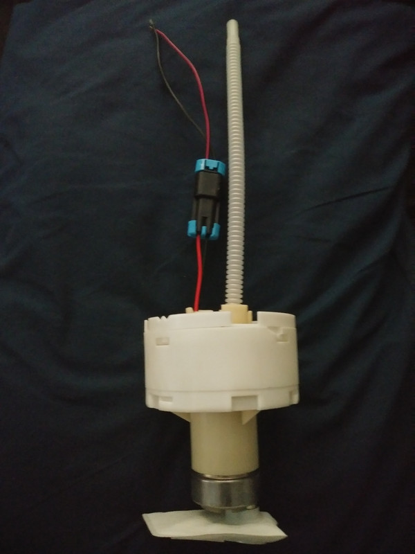
    With the fuel pump out you can now unbolt the positive and negative wires on the pump and carefully remove the other single use clamp and ribbed fuel line from the pump.

    Also I should mention that I was able to reuse that brown ribbed fuel line on my AEM pump, it fit perfectly. I believe that hose is 8mm or 5/16" so if you do need to replace yours you could probably do so with a fuel-purpose rubber hose.

    Back to parting out your fuel pump... the next thing you'll want to do is remove the top cap on your fuel pump housing. I marked mine, you probably don't need to, but why not... You then push in the 4 tabs around the outside of the housing that you see in this picture and then remove the cap.

    Then you can pull the fuel pump inner housing out of the large outer cylinder. There will be 6 rubber sleeves in there that seat the inner housing to the outer one.
    You now want to remove the plastic support piece/ring that is held onto the inner housing with 6 more rubber sleeves. Remove all these rubber sleeves. Depending on the location, some might be hard to come off so just use a flathead screw driver to pry them off.


    This is the furthest point of disassembly, now you'll want to start preparing your new fuel pump. The XS-Power fuel pump bracket is definitely the cheapest one and it works great, but it comes with 2 o-rings and there is no way your fuel pump will fit into the sleeve with those o-rings in there. So throw those o-rings away and slide your new fuel pump into the sleeve. It is important to make sure that your new fuel pump will be sitting in the same position as the old one height-wise so that your car will still keep fueling even when your tank is really low. I compared it to my old pump by doing this in the picture below so that the pickup tube on the bottom would be the same height.

    Once the pump position is where you want it, crank that XS-Power sleeve tight and your pump will be locked in there.

    With this design you won't need that ring with the extra 6 rubber sleeves, just put 6 of the rubber sleeves you removed onto the XS-Power bracket and drop it right into the big outer cylinder housing. Put the first cap you removed back on and now you have your new fuel pump-in-housing. (You will have 6 leftover rubber sleeves, the original pump design uses 12, this one uses 6).


    You can now install the ribbed fuel line onto the aftermarket pump with a hose clamp (my pump came with a new clamp).

    *Edit*
    I guess AEM fuel pumps don't come with built-in check valves so I installed an in-line check valve with some standard 5/16" fuel line hose right above the outlet of the fuel pump and now the car starts up every time. This is the check valve I used: https://www.highflowfuel.com/i-23908...-8mm-5-16.html. I was having a long cranking issue forever and come to find out, this is what caused it.


    Next is the wiring... Audi uses black as the positive/supply wire and brown as the negative/ground wire (it's a weird Audi thing). The AEM pump has red as positive and black as negative. Cut your Audi fuel pump wires at a length that still gives you some slack and solder the black Audi wire to the red new one, and brown Audi to the black new one. Ignore all the electrical tape garbage in the picture below, I changed my harness since I took this picture. Electrical tape will unwrap itself when exposed to fuel so I only used heat shrink wraps on the wires. Also it is a good idea to offset your solder connections incase for whatever reason the connections become exposed down the road. These wires will be sitting in the fuel and if they ever become exposed and contact each other, they will spark and that is bad, bad news.


    Now you can connect your "modified" wiring harness in the above picture to the new fuel pump. Then install your sock filter on the bottom of the fuel pump. This is how the AEM one is attached.

    Your new fuel pump is now ready to drop back into the tank. This part can be a little tricky because you have to get the 3 (or maybe 4, I can't remember) tabs lined up so you can click it down and then turn it to lock it. These are the tabs in the fuel tank that you need to lock into.

    You can see in this picture again that the slots on the pump housing are the ones you see on the very bottom.

    You'll want to push the fuel pump in pretty good until you think they've clicked, and then grab your fuel pump tool to turn it 10º clockwise to lock it. Pull up on it to make sure it actually locked in. I had to do this a few times until I seated it correctly and turning it actually locked it. The key is to try and have it go in perfectly straight so all 4 tabs contact at the same time. When it's locked in you'll know because you can pull on it hard and it won't come up. Reinsert the fuel level sender back into its spot, it will click when it locks in. Make sure there are no wires or anything keeping the steel level sender arm and plastic ball from moving all the way up and down. Now reconnect the wires and fuel lines to the upper white fuel tank cap and seal the cap back on the top of the tank with the black or orange lid gasket. Lock that black plastic lock ring by hammering it clockwise until it's tight or lined up with the mark you originally made. Reconnect the electrical connector and fuel lines on top and you are good to go!

    It might crank a little extra on the first start to get fuel through the lines, but mine started right up and the AEM pump is super quite! Can't wait to see how the pump performs under load!
    Last edited by b7_Andy; 03-21-2020 at 05:49 PM.

  2. #2
    Veteran Member Three Rings B501S4's Avatar
    Join Date
    Sep 09 2007
    AZ Member #
    20960
    My Garage
    01.5 B5S4 Stg III RS6's Built Longblock, Cherokee Classic 4x4
    Location
    Raleigh, NC

    Great write up! Appreciate the effort putting it together


    Sent from my iPhone using Audizine

  3. #3
    Veteran Member Four Rings Seerlah's Avatar
    Join Date
    Dec 05 2007
    AZ Member #
    23104
    Location
    A place between here and there

    Nice write up! I just want to add a few things:

    1) Be sure your fuel level is 1/4 tank or lower. At 1/4 tank, the fuel in the tank will be level with the plastic mount bracket that holds the pump basket.

    2) You can use the stock basket and the adapter isn't absolutely necessary. You just need to modify the basket bottom for the new pump (does not apply to the Bosch 044/040), then use a sleeve or o-rings to hold the pump in place.

    3) The locking tabs for the basket are offset, so the basket can only go back in one way. So when you line up the locking tabs, be sure they are lined to the correct ones. You can also shave the little locking section indents a bit to make the pump basket easier to take out next time (I don't use the tool due to me doing this. I place the open end of a long monkey wrench into one of the slits and tap it with a hammer/mallet).

    4) The electrical connection on the top of the cap gets removed by pushing the two sides that run along the channel walls. Simple needle nose pliers work fine for here. Same as the black connection on the underside. It needs to be squeezed to be removed.
    I hate it when my car acts like a little bitch, treating me like a bitch

  4. #4
    Veteran Member Four Rings Seerlah's Avatar
    Join Date
    Dec 05 2007
    AZ Member #
    23104
    Location
    A place between here and there

    Question for those who run the Walbro 274 in the stock basket. Did you guys need to cut back on the section where the pump seats? Or cutting the bottom out will suffice?

    I haven't installed the pump yet, and figure this a good place to ask (topic relevant and info can be used for those who choose to walk this route, but OP's way is much cleaner). Basically need to know if the pump sits too low when just the bottom is cut out or do I need to cut back a bit so the pump sits higher in the basket (does not bottom out on bottom of tank when installed). Thanks in advance!

    How it currently is.


    Update: Got the answer I was looking for. The Walbro 274 can be installed just how I have it pictured above, for anybody concerned if it will bottom out in the fuel tank.
    Last edited by Seerlah; 09-14-2018 at 11:26 AM.
    I hate it when my car acts like a little bitch, treating me like a bitch

  5. #5
    Veteran Member Three Rings ruiz's Avatar
    Join Date
    Apr 07 2009
    AZ Member #
    40895
    My Garage
    B5 bi-turbo avants
    Location
    MD

    Great write up bro, I'm really glad you did this

  6. #6
    Veteran Member Four Rings vavJETTAw36's Avatar
    Join Date
    Jul 04 2012
    AZ Member #
    96276
    Location
    Woodbridge, VA

    good write up.

    My only issue is that you used electrical tape and did not stagger your splices. Once the gasoline eats off the adhesive on that electrical tape, guess what is going to be touching together? Bare wire to wire = explosion.

  7. #7
    Veteran Member Four Rings vavJETTAw36's Avatar
    Join Date
    Jul 04 2012
    AZ Member #
    96276
    Location
    Woodbridge, VA

    Quote Originally Posted by Seerlah View Post
    Question for those who run the Walbro 274 in the stock basket. Did you guys need to cut back on the section where the pump seats? Or cutting the bottom out will suffice?

    I haven't installed the pump yet, and figure this a good place to ask (topic relevant and info can be used for those who choose to walk this route, but OP's way is much cleaner). Basically need to know if the pump sits too low when just the bottom is cut out or do I need to cut back a bit so the pump sits higher in the basket (does not bottom out on bottom of tank when installed). Thanks in advance!

    How it currently is.


    Update: Got the answer I was looking for. The Walbro 274 can be installed just how I have it pictured above, for anybody concerned if it will bottom out in the fuel tank.
    It would be in your best interest to remove the wire connector on those wires and just extend the wires. Ive seen a handful of guys who either found the connector to be melted to shit or left them stranded completely.

  8. #8
    Veteran Member Three Rings csobel's Avatar
    Join Date
    Mar 25 2018
    AZ Member #
    416107
    Location
    Portland, OR

    Thanks a lot, this is great!

  9. #9
    Veteran Member Four Rings Seerlah's Avatar
    Join Date
    Dec 05 2007
    AZ Member #
    23104
    Location
    A place between here and there

    Quote Originally Posted by vavJETTAw36 View Post
    It would be in your best interest to remove the wire connector on those wires and just extend the wires. Ive seen a handful of guys who either found the connector to be melted to shit or left them stranded completely.
    Thanks for the info. Will do!

    Updated: Was talking to someone who answered my inquiry about the fuel pump sitting too low, and going to butt connect (not solder) 10 gauge wire all the way to a 30a relay. So it will have 10awg wire all the way from the battery to the pump, minus small section of the pump's 12awg wire.
    Last edited by Seerlah; 09-15-2018 at 07:52 PM.
    I hate it when my car acts like a little bitch, treating me like a bitch

  10. #10
    Veteran Member Four Rings b7_Andy's Avatar
    Join Date
    Jul 18 2015
    AZ Member #
    343342
    My Garage
    Scrap Transmissions!
    Location
    Denver, CO

    Quote Originally Posted by vavJETTAw36 View Post
    good write up.

    My only issue is that you used electrical tape and did not stagger your splices. Once the gasoline eats off the adhesive on that electrical tape, guess what is going to be touching together? Bare wire to wire = explosion.
    That’s a good point about not soldering them staggered. They do have heat shrink wrap over the solder joints and then electrical tape over the shrink wrap. I’m thinking that should be enough to keep them protected.

  11. #11
    Veteran Member Four Rings b7_Andy's Avatar
    Join Date
    Jul 18 2015
    AZ Member #
    343342
    My Garage
    Scrap Transmissions!
    Location
    Denver, CO

    Thanks for the added tips @Seerlah, my tank level was less than 1/8 which made the project super clean. Definitely make sure your fuel tank is less than 1/4... I helped my buddy with some fuel
    pump stuff once and he had about half a tank and the whole time we were just working under fuel.

  12. #12
    Established Member Two Rings
    Join Date
    Jul 20 2009
    AZ Member #
    45230
    Location
    FRANCE

    Electrical tape over the shrink wrap is a bad idea, the adhesive will dissolve in the fuel, and after a while, the tape will float around in the tank.
    Twist wires + silver solder + heat shrink each wire + heat shrink both wires to keep them combined.

    12AWG wire is enough for 267/274 450lph walbro pumps but cannot be silicone insulated wire (silicone disintegrated inside fuel but very useful outside the tank: very flexible and high conductivity with the many wires inside).

  13. #13
    Veteran Member Four Rings b7_Andy's Avatar
    Join Date
    Jul 18 2015
    AZ Member #
    343342
    My Garage
    Scrap Transmissions!
    Location
    Denver, CO

    Quote Originally Posted by RC200 View Post
    Electrical tape over the shrink wrap is a bad idea, the adhesive will dissolve in the fuel, and after a while, the tape will float around in the tank.
    Twist wires + silver solder + heat shrink each wire + heat shrink both wires to keep them combined.

    12AWG wire is enough for 267/274 450lph walbro pumps but cannot be silicone insulated wire (silicone disintegrated inside fuel but very useful outside the tank: very flexible and high conductivity with the many wires inside).
    Thanks for the info! I forgot to update this, but right before I got the car running I pulled the fuel pump wiring out again to offset my solder connections and the electrical tape had already started to unwrap itself just from the fumes in the tank (tank was empty). So I cut it up and resoldered it and used only heat shrink on the wires. Been like this for a couple months now and hasn’t set on fire yet

  14. #14
    Established Member Two Rings
    Join Date
    Jul 20 2009
    AZ Member #
    45230
    Location
    FRANCE

    Heat shrink is incredibly fuel resistant, I use it for years, even in the engine compartment, used as wire sheath to protect wires (not shrunk in this case), better than the OEM spiral sheath

Tags for this Thread

Bookmarks

Posting Permissions

  • You may not post new threads
  • You may not post replies
  • You may not post attachments
  • You may not edit your posts
  •  


    © 2001-2025 Audizine, Audizine.com, and Driverzines.com
    Audizine is an independently owned and operated automotive enthusiast community and news website.
    Audi and the Audi logo(s) are copyright/trademark Audi AG. Audizine is not endorsed by or affiliated with Audi AG.