Audizine - An Automotive Enthusiast Community

Results 1 to 8 of 8
  1. #1
    Veteran Member Four Rings
    Join Date
    Nov 25 2011
    AZ Member #
    84419
    My Garage
    2018 F80 M3 ZCP, 2007 RS4
    Location
    Bay Area, CA

    DIY Injector Wiring Harness

    Guest-only advertisement. Register or Log In now!
    Our cars are old. Our wires are old. Things just aren't the way they used to be. So what's the best solution? Surgery.

    My injector wires were pretty beat up after 160k miles, and the last time I had my injectors out, after I reconnected the wiring harness my car shot a flame in my garage. The wiring harness was shorting so it was time to fix it. I wanna thank Lysergik for his DIY, I took inspiration from that, but I went a slightly different route and wanted to share. For my build, I am using EV14 Bosch injectors. So I opted to go with USCAR EV14 connectors, rather than going with oem injector connectors and using the EV14 adapter. My new harness will directly connect to the EV14's.

    Depending on your specific case, you might want to reuse the OEM injector clips, but just get new terminals that you can attach to the new wiring you will make.

    Original DIY
    http://www.audizine.com/forum/showth...or-Harness-DIY

    *Disclaimer: I am not responsible for you messing up your ECU by improperly wiring this harness. Do this at your own risk and if you have any questions please ask!

    So here's what you'll need:


    Links for everything:

    Crimp tool
    Wire stripper
    Braided sleeve 1/4"
    Braided sleeve 1/2"
    Heat Shrink
    Self-Fusing Tape
    18AWG TXL Wire (You can also use 20gauge)
    12-pin sealed connector
    EV14 specific connectors

    If you are using OEM style injectors:

    OEM injector terminals
    OEM rubber boots
    De-pinning tool

    You'll also need a heat gun for the heat shrink tubing

    You're looking at about $100 in damage for the parts. Not bad for peace of mind and a nice looking harness.


    Ok so now we're ready to get started. I WILL SHOUT LIKE THIS FOR IMPORTANT STEPS

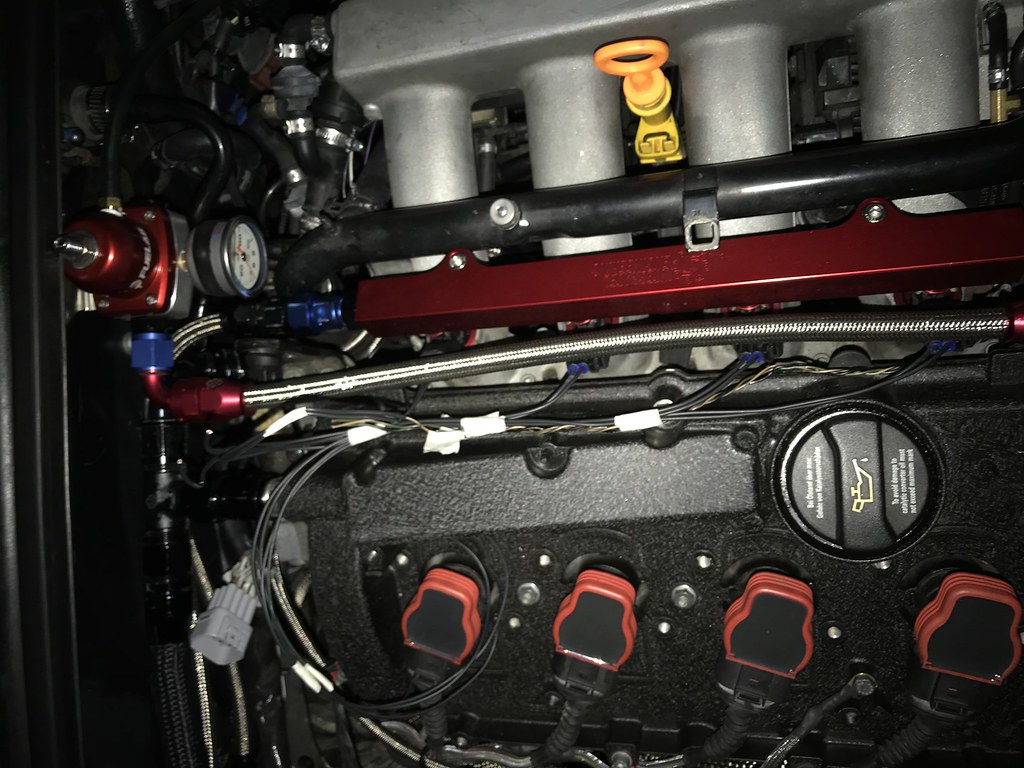
    First step is to DISCONNECT YOUR BATTERY. Then pop the hood and start disconnecting your harness. Find your cam position sensor (front of engine, right side of timing cover) connector and push in on the metal tab to release the connector. Then move over to your fuel rail and locate the metal tabs on the back of the connectors. Push in on the tabs while you pull up gently. They'll release with little effort. After you have all four injector connectors off, as well as the cam sensor connector, you can start to fish the harness back towards the rear of the engine so you can have a bit more slack when cutting the wires.


    Here you can see the section you will be working on. I fished the harness back and under my valve breather so the whole thing can lay over the coil packs.


    Using a sharp razor, begin cutting the black wiring cover to expose the 11 wires.


    You'll wanna cut a bit more than the picture above, dont worry about exposing too much wire, you can always cover that up with heat shrink/self-fusing tape.
    Once you have all the wiring exposed, grab some tape and stick two pieces on each wire, about 2 inches apart for a total of 22 pieces of tape. Then for each wire, mark the tape with the same number on both pieces. Take a look at wire #3, and do that for all 11 wires. This is crucial for determining which wires match up. You wont want to mess this step up.


    Once you have them all labeled, you can cut the wires. Cut them all at the same length. If you grab all of the wires there shouldn't be any longer than the others. Now you can begin crimping on the male terminals. Strip the ends of the wires, and slide a yellow insulator over the wire, then use the crimp tool to attach the terminals to the wires. End result should look like this. Make sure you don't pull off any of the labels in the process!


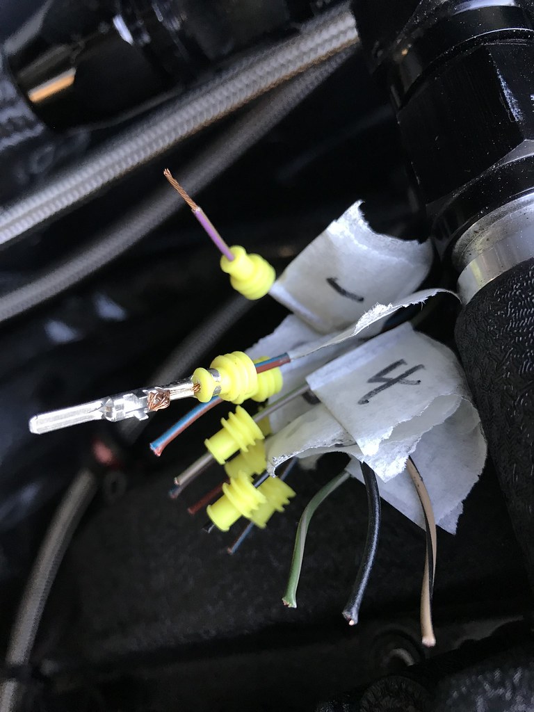
    Should look like this when you finish


    Then grab your longer male end connector and insert the terminals into the back of the connector. They only go in one way, so make sure you twist the terminals to orient them properly. You need to hear a click to ensure the terminal is properly seated. Give each wire a little tug after you insert it to make sure its snug.


    NUMBERING EACH CONNECTOR: You can insert the wires in whatever order you like into the connector. What I did was, when looking at the back of the connector, wire #1 went into the top-left slot. Wire #2 went to the right of that, and so on. Here is a diagram to help illustrate


    Now that you have your connector attached to the wires in the engine bay, you can move onto making the new harness. Take the half of the oem harness that you cut off and lay it all out in front of you. There are two wires to each injector connector, and 3 wires going to the cam position sensor connector.


    What I did was take my new injector connector, crimp on the new terminals and insulators, and take it back to the engine bay so I can mock it up and find the length I'd have to cut it. Do the same with the remaining injector connectors. SO, to make this all easier, assemble the new injector connectors with some extra length of wire attached. Then take them to the car and clip them into the injectors. Run the wires how they would be laid out and use some tape in various sections to secure the wires together. When you take it all back out you should have an idea of the lengths you'll cut all the wires to.


    The white pieces of tape near the ends of the wires are how I marked the lengths.


    I had to lengthen the wires for my cam position sensor, so I cut the green, beige, and black wires and attached longer pieces of wire. This might not be necessary for you. BE SURE TO LABEL THE NEW WIRE WITH TAPE JUST AS BEFORE


    Now you can start putting it all together. After you have the lengths of all the wires down, you can slide some heat shrink over the wires. Bundle them together and cut some of the braided sleeves to fit over the wires. So in order it goes: wires, heat shrink, braided sleeve. You can then use the self-fusing tape to seal any connection points of the braided sleeve. MAKE SURE YOU LABEL THE NEW WIRES ACCORDING TO THE EXISTING LABELS WIRES COMING OFF THE OEM INJECTORS


    Once you're done, crimp on the 11 female terminals to the new end of the harness. You should have all 11 labels still on the wires. YOU WILL NEED TO MIRROR THE POSITIONS OF THE WIRES FROM THE FIRST CONNECTOR YOU MADE. TAKE SOME TIME TO THINK ABOUT IT AND MAKE SURE YOUR NUMBERED WIRES WILL MATCH UP.


    This is the finished product!


    Congrats, you now have a working, good looking, and removable injector harness. Install back into the car, reconnect the battery, and start her up. If all is well, drink a beer

  2. #2
    Senior Member Two Rings
    Join Date
    Oct 07 2008
    AZ Member #
    33928
    My Garage
    05’ GLI 1.8T_4motion, 07’ A4 3.2_quattro
    Location
    Calgary, AB.

    Great DIY - thanks for posting!

  3. #3
    Veteran Member Four Rings Spike00513's Avatar
    Join Date
    Mar 05 2013
    AZ Member #
    110766
    Location
    CA


  4. #4
    Veteran Member Three Rings 5ktq's Avatar
    Join Date
    Aug 15 2016
    AZ Member #
    378564
    Location
    Western Canada

    You can get the terminals, seals, EV1 style connectors, etc, a lot cheaper getting them from AMP directly instead of through VW.

    Search "Junior power timer" at your favorite electronic component supplier, eg mouser, digikey, etc. 15...50 cents per crimp, depending on style, finish, quantity.

    Might be worth one of you guys buying a bunch and mailing others. (I'd offer, but being in Canada the shipping would ruin it)

  5. #5
    Veteran Member Three Rings
    Join Date
    Dec 30 2014
    AZ Member #
    306751
    My Garage
    Nogaro 2000 S4 6-Speed, Ebony Pearl 2002 A4 5-Speed
    Location
    South Carolina

    Great DIY bud, i need those crimpers!
    You win some, you lose some...

  6. #6
    Active Member One Ring
    Join Date
    Jan 05 2018
    AZ Member #
    412047
    Location
    Jersey

    Excellent write up!


    Sent from my iPhone using Audizine

  7. #7
    Junior Member Two Rings
    Join Date
    Oct 15 2018
    AZ Member #
    428939
    Location
    San Diego, CA


    Great write up and pics! I hope you are still monitoring this post, as I have some questions. I have been working off the 2014 Injector Harness writeup by Lysergik and have been hunting down the 12-pin Delphi GT 150 connectors that he used, but I have not yet made the purchase. I have an old 2002 Audi A4 1.8T B6. The fuel injector harness is much more damaged from heat than the Ignition harness, aside from the connectors. I had previously refrained from trying to tape it all up with harness tape because I was afraid that I would do more damage than good. The plastic harness casing and the insulation on the small 20AWG and 22AWG wires are cracking severly. Then a Static Open failure DTC on injector #4 happened while I was out driving last week. While investigating, just unplugging the connectors and gently lifting them up, cracked the wire insulation on most wires where they make a big angle up and then down to the injector plugs, exposing the copper. The injectors all Ohm'd out the same, leaving the harness and/or connectors as the primary suspects. I don't plan to cut the old harness or further destroy the fuel injector wiring until I have all the parts in hand to make a new harness.

    So I have been intently looking at the info for this 12-pin, sealed, gray connector sold on Amazon, in the link that you provided. I just stumbled on your post tonight while researching connectors and components. I think the manufacturer is Superseal but I am still searching for their WEB site and looking for some data sheets. I don't trust what is posted on Amazon at all, much less buying auto parts from any of their sellers. I noticed in the details of the Amazon post, that this connector is spec'd for a limited temperature range of -10 to +80C, which isn't ideal for use in the engine bay depending on how far you distanced the connectors from the engine.

    1) Have you had any issues with this connector since you installed it?

    I bought an Ignition Wiring Harness from ECSTuning last year but haven't installed it yet. I had replaced my coil pack connectors and in the process broke wire insulation on 2 wires of one connector, but my fix with both liquid insulation and some small pieces of heat shrink has seemed to hold up pretty well. My point about the custom-made ECS harness: this gray Polyseal PA-66 12-P connector of yours looks amazingly similar. Any chance this was the inspiration for picking this connector? I'm less certain if the pins are the same though. I was hoping you would show some pics of the female pins connected to your injector harness, as the female pins that ECS supplied have no locking tabs on the sides to anchor them into the connector housing. I'm not sure how they would stay in, except for the seals. I am just trying to evaluate this connector if it is indeed the same brand. also I noted, the ECS harness has the the opposite orientation for male/female connectors than yours - you have the male-terminal plug side connecting to the engine wire harness. Was that an arbitrary decision or a reason behind it? The two halves of the connector are not symmetrical - the male pin side has a long enough extension that you can put heat shrink around it and protect the wire access to the pins; the female pin half looks like it was meant to just clip into a chassis and let the wires hang.

    2) Were your female pins different from the male pins for this connector, with respect to the retaining system? I can't discern any locking tabs on either the male or female terminals in the Amazon photo. The dimensions also do not match but I expect the dimensions in the photo are probably incorrect. The male plug with female pins is 23mm high on the ECS harness. The height of the connector with male pins is the same for both - 40mm. The widths could be 28mm depending where they are measured. Sorry if I there is any confusion, but I have been referring to the plug with female pins as the female connector (even though it is technically the male plug) and similarly, I name the mating connector based on its male pin gender. I guess if ECS thinks this is an adequate 12-pin connector for their product, then I am probably OK with it, assuming they are the same.

    3) Did you replace the connector and wires for the Cam Position Sensor? You didn't say much about this. If so, where did you find the replacement connector and pins? I do know the 3 pin (female pin) connector housing is still sold by Audi. I doubt that I can reuse my existing CPS wires. The harness cover is as hard as a rock all the way to the CPS connector; it doesn't flex at all, and will be hard to cut off. The connector housing could be re-used, but I need to find replacement pins. To the best of my knowledge, the dealer does not sell the pins anymore. They do sell a wire with unspecific pins on each end that you can cut in half. The $29 price is ridiculous, and you only end up with two pigtails of about 6". My CPS plug is a metal clip-style, 3-pin connector similar to the Injector connectors.

    4) New injector connectors: So looks like you made a "find" for your injector connector pig tails which are really, really long. I am envious . I was not clear if you changed your fuel injectors from stock, or if those are the original connector types for the injectors that came with your engine. So I have 2-pin connectors with metal clips for my stock EV12 Fuel Injectors. I did find and buy some Bosch 1-287-013-003 Injector Terminal Repair Kits at a very reasonable price of $9ea from AutohausAZ.com. They come with a similar 2-pin, metal clip connector, 2 female terminals, and a rubber tail "grommet". So it's cheaper than the dealer price for the grommet alone. The terminals for this connector do not come with seals though (square holes). Actually, I'm not sure about the OEM connectors - I haven't torn my old wire harness apart yet, as I want to still swap out fuel injectors and replace the o-rings and possibly debug the injector failure further, by just covering up the broken wire insulation with some liquid insulation.

    With regards to wire gauges on the existing harness: I noted that you mentioned you were switching the harness on the injector side to all 18AWG TXL wire. Nothing wrong with that; it will probably survive the heat longer. It looks like the terminals of the Polyseal connector are made to accommodate a wide range of wire sizes from 17AWG to 22AWG (too wide IHMO) . I noted though in Lysergik's write-up, that he mentioned some issues crimping the smaller wires of the engine harness to terminals, sufficiently tight so that the don't pull loose. I am actually considering crimping+soldering, although I just read a post earlier saying that Audi frowns upon solder connections. It's hard to get that through my thick Electrical Engineer skull, but I will likely do it for just the crimps of those small AWG wires. The RED/BLU wires which are tied together in a common circuit internal to the engine wire harness before it meets the ECU, and supply 12V (from the Fuel Pump relay) to the fuel injectors, are truly 20 AWG. The Bentley wiring diagrams show these as 0.5mm2 wires, which corresponds to 20AWG. I measured the existing wires and although I am sure the insulation thickness has probably shrunk to some extent due to heat, the OD of the thicker wires is about 1.7mm, which is very close to the listed 2.8mm OD of 20AWG TXL wire. The four individual Pull Down wires, from the ECU to each Fuel Injector, I measured an OD of 1.2mm. The Wiring Diagram calls them out as 0.35mm2 wires which corresponds to 22AWG gauge, but they seem smaller, closer to 24AWG. TXL 22AWG wire should have an OD of 1.6mm. So did you encounter any difficulties getting a good crimp on the smaller wires with the Polyseal terminals? The pins of the Delphi GT 150 connector that Lysergik used were spec'd for 20-22awg wire (I'm assuming he used those, but he had four different packages of pins in his photo and didn't list the P/Ns that were used). You can buy different pins and seals for larger diameter wires, that all fit the same GT-150 connector housing. The next larger terminal crimp and seal is for 18-20AWG wire. They have seals down to 14AWG. Did your seals fit snugly around these smaller, presumably 24AWG, wires?

    Anyways, thanks for tip about laying out the wires connected to the fuel injectors and taping them in place, before cutting the final length to the female-terminal connector. I was trying to visualize in my head how I would do that. I was also thinking about routing them so that they do not lay in contact with the valve cover. I'm not sure which gets hotter - the valve cover or the manifold and coolant return pipe on the other side. I've decided that the plastic engine cover/beautifier/silencer traps heat around the fuel injector and ignition wire harnesses, and ultimately only achieves their premature demise.

    One last question - at what distance away from the valve cover does the wiring to the main engine harness branch become flexible again? I would like to locate the connector closer to the branch in the main harness, somewhere in the space between engine and the firewall, if there is sufficient access for the tedious work of cutting, stripping and crimping wires tiny wires. I was thinking with the coil packs and temperature sensor disconnected, the engine harness could be pulled up a bit to work on. Then I just need to figure out a way to lie down over the engine.


  8. #8
    Junior Member Two Rings sgudino's Avatar
    Join Date
    Jul 07 2012
    AZ Member #
    96431
    My Garage
    Mazda RX-8
    Location
    California

    so how did it go with the harness? I had a CCT issue and in the process of swapping out the parts, i lost signal to the camshaft position sensor. most likely a crack in the line in the signal as I have power and 5.0V going through the wire, just cant see timing on the vagcom 093. I will need to make this change in order to pass smog in January. what components did you buy.
    Sergio
    2002 Audi A4 B6
    2004 Mazda RX-8
    1997 VW Jetta GT

Bookmarks

Posting Permissions

  • You may not post new threads
  • You may not post replies
  • You may not post attachments
  • You may not edit your posts
  •  


    © 2001-2025 Audizine, Audizine.com, and Driverzines.com
    Audizine is an independently owned and operated automotive enthusiast community and news website.
    Audi and the Audi logo(s) are copyright/trademark Audi AG. Audizine is not endorsed by or affiliated with Audi AG.