


What I did: Replaced all planned-obsolescence items for suspension and drivetrain mounts on the front half of the car.
Why I did it: To refresh the feeling of the car and prolong its life. There was so much creaking and knocking anytime I went over a bump or turned the wheel to the point of being embarrassing.
*Disclaimer: I am not a certified mechanic by any means so this guide is to be used for reference on how I did it. Perform this work at your own risk and I am not liable for any issues or injuries that may occur. I used mainly aftermarket parts which all came in perfect condition and fitment, however I cannot speak for the durability as I just complete the job.
Items Replaced w/ part numbers:
-Engine Mounts- ES#: 2816259 nuts(4)- ES#: 471073 washer(2)- ES#: 470401
-Transmission Mounts- ES#: 2952012
-Subframe Bushings- Front ES#: 2708247 Rear ES#: 2594425
-Inner Tie Rod Ends- ES#: 2580517
-Outer Tie Rod Ends- ES#: 034-406-2018
-Control Arm Kit- 034-401-1004
-Sway Bar bushings- ES#: 376113
-Struts- ES#: 2981791
-Strut Bushings- ES#: 2954139
-Long Subframe Fasteners (4)- ES#: 251990
-Engine Mount Bracket Fasteners (4)- ES#: 8639
-Transmission Cross Member Fasteners (4)- ES#: 471298
Tools Needed:
-Metric wrench and socket set w/ extensions and breaker bar
-Torx Bit Set
-Torque Wrench
-Vice Grips
-Long Bladed Screwdriver
-Hammer
-Pickle Fork
-Press/Handheld bushing press
-Bushing Press Kit
-Hoist, chains, hook
-Jack, Jack-stands
-Metric Allen Wrenches
-Thread-locker Blue
-Copper Anti-Seize
-3 PVC Threaded Coupler
-MacPherson Strut Compressor (Rental)
-Right Angle Attachment (optional)
NOTES BEFORE STARTING:
-Spray every fastener with penetrating fluid
-Always try to remove fasteners with hand tools. Impact is quick but can break fasteners and cause more work and frustration.
-I used thread locker on every set of threads except on the inner and outer tie rod ends, for which I used anti-seize.
Process Layout:
STEP 1: Disconnect Control Arms/Tie Rods
STEP 2: Remove Struts
STEP 3: Remove Sway Bar
STEP 4: Remove Subframe
STEP 5: Replace Transmission Mount
STEP 6: Replace Engine Mounts
STEP 7: Replace Inner Tie Rod Ends
STEP 8: Replace Subframe Bushings
STEP 9: Install lower control arms to Subframe and Reinstall
STEP 10: Rebuild Struts and Install
STEP 11: Finish Control Arm Installation
STEP 12: Install Sway Bar
STEP 13: Final Torque & Assembly
STEP 1: Disconnect Control Arms
Put the front of the car on jack-stands and remove front wheels and belly pan. Remove all nuts and fasteners attaching control arms and outer tie rod end to knuckle. Separate outer tie rod end from knuckle and loosen retaining nut locking it to the inner tie rod end. Unscrew OTRE from ITRE while counting the turns. (New OTRE will later be installed with same number of turns for rough alignment until professional alignment is done.) Separate Upper Control Arms from knuckle. The combination of a pickle fork and hammering the outer end of the control arms will break them free. AVOID wedging the opening of the knuckle as it can cause damage to knuckle $$. Lower control arm ball joints can be rotated with a small hex key to help but they stripped out when I tried. After breaking the LCAs free of the knuckle, leave them in the knuckle to support assembly during next step.


STEP 2: Remove Struts
Remove lower strut fastener from lower control arm. *If knuckle sags, ensure to support it to avoid tension on brake lines and CV joints. In engine bay, remove Cabin Air Filter access housing (pull back weather strip and it comes out). Move the coolant expansion reservoir by removing 1 screw, then pull back (towards front of car) and up to slide reservoir out of 2 clips on backside, set aside. Locate the 3 upper strut bolts that you now have access to. One bolt on each side will be covered by a plastic cap. Remove all 6 bolts and remove struts from car. There may be a retaining clip near the top of the spring that will have to be pried off (this was used for original assembly and will not be reused.)


STEP 3: Remove Sway Bar
Remove upper fastener (1 per side) that connects the sway bar end links to the straight lower control arm. Remove 4 nuts holding inner sway bar brackets and the bar can be removed.
STEP 4: Remove Subframe
*By removing the subframe, you are removing ALL support for the engine and transmission. You must use a safe and reliable way to support both during the following steps. I put a jack stand under the transmission and a crane on the front engine pulling bracket. This could be achieved with an engine hoist but I would try to get it from the top. Just jack stands under the entire powertrain seems risky, but possible. You will need to be under the car for the next steps so if something goes wrong YOU WILL DIE!


After supporting engine and trans, remove sub mount and stop bracket. Remove three fasteners holding the transmission bracket to the transmission. Take measurements or mark the position of the subframe to the body wherever is easy for you to identify. (These will be used to locate the subframe during reinstallation.) The subframe is fastened to the body along with the two engine mount brackets and transmission support frame, thus they will all be unfastened. Support knuckles and fully disconnect LCA ball joints as the LCAs will come off with the assembly. Remove the 2 13mm nuts on the bottom of the engine mounts (mark which hole of the EM bracket is being used for EM) and 12 fasteners from the subframe, engine mount brackets and trans support. If doing by yourself (not recommended) remove 6 rear fasteners first, support front of subframe with jack, remove front 6 fasteners and lower assembly on jack.


STEP 5: Replace Transmission Mount
Remove 2 nuts holding trans mount to trans support frame. Remove 3 fasteners holding trans mount bracket to trans and remove. Support frame can remain in place resting on exhaust/driveshaft. Remove long fastener holding mount to mount bracket. Install new trans mount to bracket and cross frame. Some people recommend JBWelding the nut to the bracket because you cannot access it when it is mounted to the trans. This is a great idea to help the reassembly of the cross frame but I never use the stuff. If you do; you can keep the center fastener finger tight until the subframe and cross frame are fully installed, then tighten. If you dont; make the center fastener finger tight, mount to cross frame and mount cross frame to body with just the 4 shorter fasteners. Rotate the transmission mount bracket to line up the fastening holes on the trans. Unfasten cross frame and carefully remove mount and bracket from frame and torque the center fastener of the transmission mount.


STEP 6: Replace Engine Mounts
Drivers side is no problem. Remove 13 mm nut from above and reinstall new mount. Not the orientation and be sure to reinstall properly. Passenger side: Bi%@h. Remove engine air cleaner box. Manipulate turbo/exhaust heat shield to get access to nut. Get clever here, the objective is simple. I think a flex head 13mm ratcheting wrench would handle this but I was determined to do this without buying a whole new set of wrenches. I made the tool below.


STEP 7: Replace Inner and Install Outer Tie Rod Ends
Remove outer boot clip with pliers. The inner pinch clamps can be removed by prying a long slotted screwdriver into the loop. Carefully slide the boot off. Remove the ITRE with a wrench if you have it or I used a big pipe wrench. Reinstall new ITRE. I installed the boot (replace if torn) with a worm gear band clamp on the inside with a DeWalt right angle attachment on a drill and reused the outer boot clip.
Thread the new OTREs to the same count as when they were removed. Hand tighten retaining nuts for now.

STEP 8: Replace Subframe Bushings
My 20-ton press and kit are the only things I have from Harbor Freight and they work really well surprisingly. I used gooheads advice on using a 3 PVC threaded coupler to support the subframe which I couldnt believe held up to the pressure and worked perfectly. *goohead also has a write up for using a handheld bushing tool. http://www.audizine.com/forum/showth...bframe-bushing
The front bushings are installed with about a 3/16 gap from seating flush. The rears are pressed flush. They are pressed in from the bottom and the slots of the bushings are to be perpendicular to the length of the car for alignment purposes. I used a silicone grease on the leading rubber edge of the bushing to avoid tearing. Ensure this rubber lip pushes fully through the subframe hole.


STEP 9: Install New LCAs and Reinstall Subframe
*The fasteners that mount the LCAs to the subframe can only be insterted/removed while the subframe is either lowered or removed from the car, they will come in contact with the body.
Loosely install LCAs to subframe. Lift rear of subframe so that rear bushings sit on trans cross frame. Use jack under front of subframe to raise into place. Start the treads on the 2 long rear subframe fasteners to support. Hold EM brackets in place and start threads on long front subframe fasteners. Ensure EMs go through same holes of EM brackets and thread in 4 remaining front fasteners and 2 nuts on engine mounts. Loosely thread in 4 rear remaining fasteners through the trans cross frame. Install and torque 3 trans mount bracket fasteners to transmission.
With the subframe fasteners still loose, there should be side to side play in the subframe. I dont have a Maintenance guide so there might be a method for aligning the subframe, but I just did my best to get it in the same position as it was before I removed it from my measurements. I tightened the subframe fasteners to about 75% of their torque values to make them tight without stretching so the alignment shop can make adjustments if necessary.
Put the LCA ball joints through their respective holes in the knuckles and thread on the retaining nuts. Continue to support knuckle assembly.
Remove drivetrain supports and reinstall snub mount and stop bracket.

STEP 10: Rebuild Struts and Install
Remove upper control arms from upper strut bracket. Install new UCAs and torque fasteners with the control arms perpendicular to the shock. The warranty on control arms will indicate a void if the arms are torqued at a position other than ride height. I wouldnt have been able to fit my torque wrench on the fasters with the strut assembly installed so I torqued them in the position (mentioned above) they were in pictures of the arms at ride height before removing anything.
Use a MacPherson Strut spring compressor to remove tension from the upper shock nut. There are several specialty tools for removing this nut but I used a deep socket in the jaws of vice grips and an allen wrench through the socket. The need for this is so that you can access the shock shaft to keep if from rotating as you remove the nut. Reinstall spring on new shock and fasten top shock nut with new upper strut bushing. Obviously can't use a torque wrench here so I made it as tight as I felt the only nut was. Remove spring compressor.
Lift the strut assembly into place and hand tighten the 3 fasteners on each side through the engine compartment. Manipulate the knuckle position to align the lower strut mount and insert the fastener and hand thread the nut on. This will now support the knuckle assembly so you can remove your supports.
STEP 11: Finish Control Arm Installation
Raise knuckle with a jack as high as you can without lifting the car off the jack-stands. Use an allen key to align the slot on the OTRE ball joint with the bolt path of the knuckle. Seat the OTRE into the knuckle and install 2 fasteners per side. *If the horizontal fastener does not push through, the OTRE slot is most likely not aligned. Seat the upper control arms and install the fastener. This fastener runs through the grooves on the ball joints to secure them in place. If the fastener will not push through the knuckle, the ball joints are most likely not fully seated yet. Torque all upper control arm outer fasteners, OTRE fasteners and retaining nuts so ITRE. Getting the ball joints in place can be difficult. Move the ball joint to match the angle of the hole in the Knuckle and I used huge Channel Locks to pull the arm and knuckle together.
STEP 12: Install Sway Bar
Loosely thread lower sway bar end link fasters. With new bushings installed, lift the sway bar into position of the body mounts and loosely install brackets with nuts. Swing sway bar up so that upper end link fasteners can be installed through lower straight lower control arm mounts. Use a jack to lift the knuckle as much as possible before lifting the car and torque down the sway bar end links and lower strut fasteners. Do this for each side. These fasteners are difficult to access with the wheels on so this gets them close to ride height for torqueing. Wait until car is sitting on its wheels to tighten the body mount sway bar brackets.
STEP 13: Final Torque and Assembly
Torque lower control arm outer fasteners. Install wheels and lower off jack-stands. Torque the body mount sway bar brackets, Upper Strut Mount fasteners, lower control arm inner fasteners to subframe.
Replace 2 upper strut mount fastener caps. Reinstall coolant expansion reservoir and 1 fastener. Reinstall cabin air filter housing and weather stripping. Reinstall engine air cleaner housing. Reinstall belly pan.
Get your car to an alignment shop-use your judgement on how to do that safely. Make sure to mention what you did and to look over the subframe alignment and torque all subframe fasteners when finished.
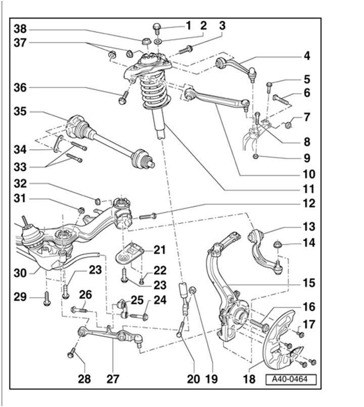
1- 75nm
5- 7nm
7- 45nm
8- 40nm
12- 70nm +180
14- 110nm
17- 10nm
20- 90nm
22- 55nm
23- 110nm +90
24- 40nm +90
26- 40nm +90
28- 70nm +180
29- 75nm
37- 50nm +90
38- 50nm
CONCLUSION:
Its tough to spend money on a car in this position (especially because this is all to keep it completely stock) but after I got great results from Blackstone Labs on their take on the condition of my engine, I decided to go for it. The subframe bushings and transmission mount looked fine but I wouldn't want to drop the subframe again in the future. It is really amazing the difference in how the car feels. The only regret I have is not spending more money on engine mounts. The RS4 mounts from ECS were cheap but I definitely feel closer to the engine. It is a nice feeling to go over speedbumps and turning lock to lock in complete silence.

 Reply With Quote


Bookmarks