I don't have a routing diagram, but I have component location diagrams. I didn't upload them all because I am too lazy, this is the essentials.
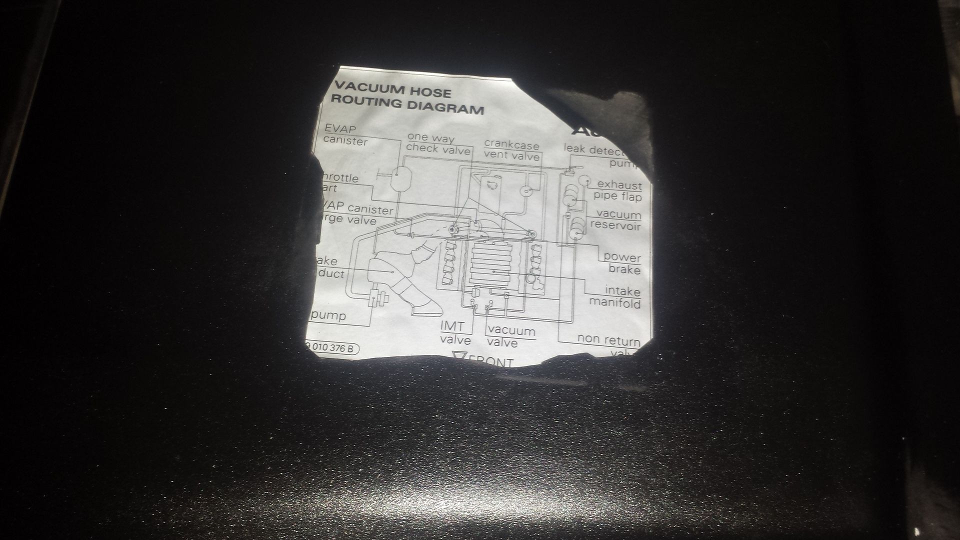
Here are the common vacuum connections in engine bay: Look at the Black Arrows for connections

#4 in this image

1 - Evaporative Emission (EVAP) canister purge regulator valve N80
Evaporative Emission (EVAP) canister purge regulator valve N80
2 - Mass Air Flow (MAF) sensor G70 with Intake Air Temperature (IAT) sensor G42
3 - Connector console
Pin assignment
Assignment of holder for connectors (right side)
4 - Valve 1 for camshaft adjustment N205
Rear view
5 - Camshaft Position (CMP) sensor G40
Cylinder bank 1
Rear view
6 - Engine coolant temperature (ECT) sensor G62
At coolant pipe behind cylinder head, bank 1
Rear view
7 - Fuel supply line
8 - Throttle valve control module J338
With Throttle drive (power accelerator actuation) G186 , Angle sensor -1- for throttle drive (power accelerator actuation) G187 and Angle sensor -2- for throttle drive (power accelerator actuation) G188
Rear view
9 - Oil pressure switch F1
Rear view
10 - Camshaft Position (CMP) Sensor 2 G163
Cylinder bank 2
Rear view
11 - Connector console
Pin assignment
Connector console beneath coolant expansion tank
12 - Valve -2- for camshaft adjustment N208
Rear view
13 - Engine Speed (RPM) Sensor G28
In transmission housing above ring gear
14 - Ignition coils with output stages
Cylinder bank 2
15 - 3-pin connector
For Knock sensor 3 G198
For Knock sensor 4 G199
Front view
16 - Secondary Air Injection (AIR) Solenoid Valve N112
Front view
17 - Intake Manifold Change-Over Valve N156
Front view
18 - 3-pin connector
For Knock Sensor (KS) 1 G61
For Knock Sensor (KS) 2 G66
Front view
19 - Ignition coils with output stages
Cylinder bank 1
20 - Secondary Air Injection (AIR) Pump Motor V101
Installation location of Fuel Pump (FP) Relay J17
Position - arrow 1 - on 9-position relay carrier on left of drivers footwell.
1.1 - Coolant Circulation Pump Relay J151 (hot countries only)
1.2 -Not used
2 -Secondary Air Injection (AIR) Pump Relay J299
3 -Motronic Engine Control Module (ECM) Power Supply Relay J271
4 -Relay for automatic transmission
A -Engine electronics fuse S282
B -Secondary air pump fuse S130
C -Not used

Assignment of holder for connectors (right side)
1) 6-pin connector for Heated Oxygen Sensor (HO2S) G39 and Oxygen Sensor (O2S) Heater Z19 before catalytic converter, bank 1
2) Connector for starter (terminal 50) and generator
3) 2-pin connector for camshaft timing control, bank 1
4) 4-pin connector for Oxygen Sensor (O2S) Behind Three Way Catalytic Converter (TWC) G130 and Oxygen Sensor (O2S) Heater 1 (behind Three Way Catalytic Converter (TWC)) Z29 , bank 1
Intake Manifold front
1 Vacuum unit for intake manifold changeover
2 Knock Sensor (KS) 1 G61
3 Knock Sensor (KS) 2 G66
4 Intake Manifold Change-Over Valve V156
5 Secondary Air Injection (AIR) Solenoid Valve N112
6 Knock sensor 3 G198
7 Knock sensor 4 G199
1) Valve -2- for camshaft adjustment N208
2) Camshaft Position (CMP) Sensor 2 G163 , cylinder bank 2
3) Oil pressure switch F1
4) Throttle valve control module J338
5) Engine coolant temperature (ECT) sensor G62
6) Camshaft Position (CMP) sensor G40 , cylinder bank 1
7) Valve 1 for camshaft adjustment N205

Secondary Air Injection (AIR) Pump Motor V101
Leak detection pump (LDP) V144


| JHM 93 Tune | Piggies | Custom Magnaflow 2.5" x-pipe non-res | ECS Solid MM | Apikol Snub | JHM Intake Spacer | K&N Drop-in | NGK BKR6EIX| 5W-30 Castrol - SOLD BUT NOT FORGOTTEN!

 Posting Permissions


 Reply With Quote

Bookmarks