


Link to the instructions, with photos
Also, posted here:
Parts
1) Radio removal keys; I went with the Xtenzi‐branded Double‐DIN keys for Audi/VW/Merc: http://www.amazon.com/gp/product/B005IBKI1W, about $10
2) An IDE SSD or HDD of your choice; I went with a 64GB Transcend PSD330 2.5‐inch IDE Internal SSD Solid State Disk (MLC Flash) but had major instability issues with it; I ended up switching to a bigger version of our drive, the MK8050GAC and then its 5400RPM Seagate version, the ST980818AM; please be very careful where you buy either one, there are a lot of scammers out there
3) USB‐to‐IDE connection cables (having two on hand allows for direct drive copying); I went with Sabrent USB 2.0 TO SATA/IDE 2.5/3.5/‐INCH Hard Drive Converter With Power Supply & LED Activity Lights: http://www.amazon.com/gp/product/B00CPGYNV4, about $15 each
4) A T8 six‐point bit (and driver) to remove all the screws
5) VMWare Player, to run the QNX Rear‐Time OS (free download): https://my.vmware.com/web/vmware/fre...re_player/7_0; for OSX, youll need Fusion and you can get going with just the trial period
6) QNX 6.5.0 SP 1 Neutrino Runtime environment (you dont need the entire SDP; free download): http://www.qnx.com/download/feature....rogramid=23665 (I realize QNX may have taken this down; either search the web or contact me for a copy)
First, remove the radio from the dash. Insert the radio keys into the slits circled in red:
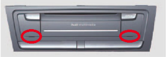
The notches on the radio keys will need to face inward (each other) and youll know you inserted them correctly as theyll click (youll feel springs being loaded). Pull on the keys and the head unit will just pop out (at this point its mostly held in place with friction from the surrounding dash trim).
As you pull the head unit out, there will be a slew of cables still attached to it:
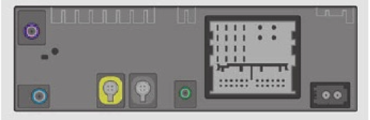
Not shown in this picture are any cables attached to the trim just below the radio key slits (Audi Drive Select, Stability/Traction Control On/Off, Hill Descent Control, etc). Youll want to get those disconnected first. The ones shown in this graphic are (from right to left): a fiber‐optic (caution: laser!) in/out cable with corrugated plastic sleeves (important), a multi‐cable/purpose carrier connector, a yellow and green four‐prong cable, and the XM/radio antenna. All except the carrier have a small latch  you have to depress before pulling on the cable. Take your time, each is slightly different. Youll need nails, too (so, nail‐biters need not attempt this). Dont pull hard on any of them as it means youre doing something wrong. Pulling too hard on the first cable I described (with the plastic sleeves) can cause the corrugated plastic to pop off even though the connector is firmly in place. So, look for that small latch before you start pulling. Now, the really large multi‐purpose cable is like a lego construction of four different connectors, all in one. Theyre held together in a carrier that swivels out. The release is on the bottom of the square and as you lift it up, it comes out of the head unit. When re‐inserting, remember to fully extend the carrier, connect with the head unit, and then swivel it down for it to lock into place.
Second, open the MMI head unit. By now you should be looking at this:
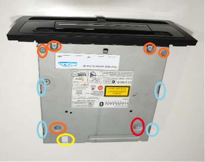
Remove the six screws circled in red with the T8 six‐point bit. Notice the darker red circle where the screw has a little neighbor; thats some sort of a pin that worried me at first; it may just be some sort of reset mechanism but it ended up being inconsequential). Break the seal circled in yellow. I tried to get crafty and avoid breaking it but it wasnt worth bending the metal flaps in the back. Use your fingers to pry open the front of the cover and work your way back, toward those flaps. You can insert a small flat screwdriver in the areas highlighted in light blue. Only insert a millimeter or two as to not damage any of the electronics inside. Just rock the blade side to side to pop the cover, as if opening a can of paint.

Third, remove the hard drive. By now you should be looking at the insides of the head unit:
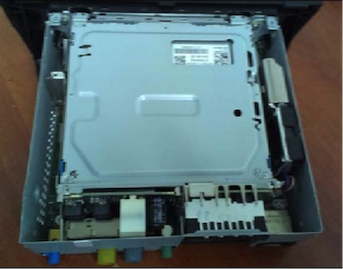
Thats the optical drive youre looking at and its not secured at all (as it was held in place by some of the screws that also held the cover in place), so, be careful! Theres a ribbon cable attached to it so gently pick it up and flip it over in front of the head unit (where the plastic dash trim is). Lay it down and out of the way. You should be now looking at this:
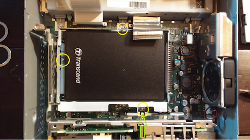 
I did not remove the DVD cable (left) or that aluminum ribbon (right) as I didnt find either to be in the way. Just remove the three screws (circled in yellow) that are holding the hard drives chassis down. Youll need to tilt the head unit up from the rear and unscrew them from the bottom of the chassis. Be mindful of the optical drive, if still attached. Where the green arrow points in his picture above, theres a little metal pin that is sticking out and holding the hard drive chassis down. Youll want to apply some light leverage with a small flat‐head screwdriver between the screw and the pin and push that pin inward and away from the hard drive chassis. Its only the third to last thing keeping that drive down. The second to last thing keeping it down is some blue heat spreader stuff glued in four specific places on the bottom of the hard drive chassis. And finally, the IDE angled‐male‐to‐male adapter at the front of the hard drive is holding it down. Once the afore‐mentioned pin (3rd to last) is out of the way, youll want to gently pry the hard drive chassis out of its little fox hole, careful to not break the IDE connector (not so much the angled adapter but the one soldered to the circuit board that the angled adapter is plugged into). The angled adapter ought to stay attached to the drive.
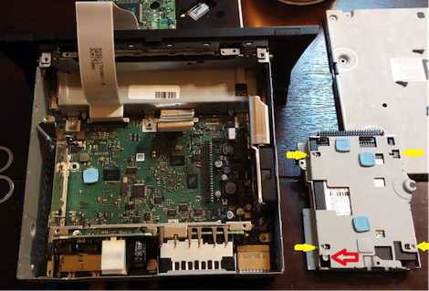
Finally, remove the hard drive from the chassis by unscrewing the four mounting screws on the sides where the yellow arrows are indicating (dont touch the ones on the bottom that are actually PART of the hard drive). These mounting screws were T‐T‐T‐T‐TIGHT but you will not need to tighten them that much on the SSD. Push the drive down so that it will disconnect from the angled IDE adapter. The adapter will probably just fall off at this point as theres nothing else holding it in place. FYI, some of that blue heat spreader stuff may stick to the hard drive chassis and some may stick to the circuit board.
Interesting factoid, once you remove the hard drive, youll notice a little flap on the bottom side of the chassis thats bent inward, right along the narrow edge opposite the angled adapter opening (indicated by the red arrow in the picture). I dont know WHY they chose to bend it inward but it presented quite the WTF? moment when I inserted the new SSD drive as it blocked it from lying down flush (one of the mounting screw holes was not aligned properly). Just grab some needle‐nose pliers and straighten that flap out. If you look on the circuit board (at approximately the same location), theres really nothing sticking out that required that flap to point inward. Just make sure its flat and not pointing down (and thus not digging into the circuit board).
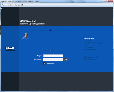
Fourth, clone those drives! You can start VM Player by double‐clicking on the .vmx file in the 650SP1‐ VM folder (I used WinRAR to extract the files from the .tar archive). In order for the QNX RTOS to boot up, you dont have to do anything. Just let it go through all its motions until you end up with this:
You will want to connect the two drives to the USB/IDE adapters and then the adapters to your computer. Make sure those featherweight drives dont go flying from any tension in the cables. Your computer will try to recognize the new drives, just ignore the messages that pop up. In the VMWare Player window above, just click the Player dropdown, select Removable Devices, find the cryptically named USB/IDE adapter name (e.g., JMicron/JMicron USA USB to ATA/ATAPI Bridge; mine wasnt obvious for the adapters I used either, dont worry), and click Connect (Disconnect from Host). This will transfer control of those USB devices to the QNX VM.
NOTE: If you dont see any USB devices, simply go to Player ‐> Manage ‐> Virtual Machine Settings, and in the Hardware tab click Add to add a USB Controller to the profile. You may need to restart the VM for that change to take effect. Then retry the previous instruction.
At this point it may behoove you to unplug and reconnect the USB adapters to your computer. The control will again go back to the VM. In fact, any time something isnt quite right, I found that reconnecting the drives helped the QNX OS recognize them better.
Click the Superuser icon. Theres no password and youre immediately logged in. Mouse and keyboard control are now passed to the QNX VM. If you need to return control to your computer, simply press the combination Ctrl‐Alt. Click the Launch (Start) menu in the bottom left, then select Utilities, then Terminal. This will start a Korn shell session. Type
Code:
mount
Code:
df
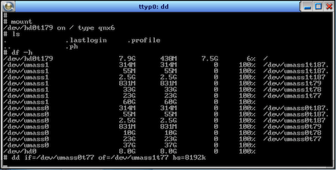
(NOTE: If you see /dev/hd10 and /dev/hd20 instead of /dev/umass0 and /dev/umass1, disconnect and reconnect the USB<‐>IDE adapters). One set (umass0) is for the MMI hard drive and the other is for your new SSD (umass1) but the order or naming will differ depending on your setup. Youll be able to tell them apart by the sheer size (expressed by default in cylinders unless you enter the command
Code:
df h
Code:
fdisk
Code:
fdisk /dev/umass0
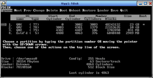
You should see the following values for your Audi MMI drive:
| 1 | QNX | 77 | 0 | 3002 | 3003 | * |
| 2 | QNY | 78 | 3003 | 4381 | 1379 | |
| 3 | QNZ | 79 | 4382 | 4487 | 106 | |
| 4 | Ext'd | 5 | 4488 | 4863 | 376 | |
| 4.1 | nonQNX | 187 | 4488 | 4816 | 329 | |
| 4.2 | nonQNX | 187 | 4817 | 4823 | 7 | |
| 4.3 | nonQNX | 187 | 4824 | 4863 | 40 |
Now press Q to Quit. Run fdisk for the new SSD drive. The first time, youll need to run it with the z argument to zero out the partition table: e.g.,
Code:
fdisk ‐z /dev/umass1
| 1 | QNX | 77 | 0 | 3002 | 3003 | * |
| 2 | QNY | 78 | 3003 | 7300 | 4298 | |
| 3 | QNZ | 79 | 7301 | 7406 | 106 | |
| 4 | Ext'd | 5 | 7407 | 7782 | 376 | |
| 4.1 | nonQNX | 187 | 7407 | 7735 | 329 | |
| 4.2 | nonQNX | 187 | 7736 | 7742 | 7 | |
| 4.3 | nonQNX | 187 | 7743 | 7782 | 40 |
Code:
dd if=/dev/umass0t77 of=/dev/umass1t77 bs=8192k
The tricky part comes when copying the Jukebox partition (78). First you need to format it:
Code:
mkqnx6fs T media /dev/umass1t78
Code:
mount r t qnx6 /dev/umass0t78 /mnt/jukebox0
Code:
mount rw t qnx6 o sync=optional /dev/umass1t78 /mnt/jukebox1
Code:
cp R /mnt/jukebox0/* /mnt/jukebox1


 Reply With Quote
 ...ordered!!


Bookmarks