


I started with this:

Then I cut off the longer of the two connectors for the ECU. I found that I needed the following wires/pins:
Pin #1 -Black/Blue
Pin #2 -Brown
Pin #3 -Red
Pin #19-Green/Black (the "K-line")
Pin #43-White/Black
I separated those 5 wires, trimmed off the rest, and sealed it back up

From the OBD connector, you just need the Green, Red/Black, and the Brown(Just to clarify, as there are two browns right next to one another, I used the one to the right in this picture)

As for the wiring, you need combine the Brown wire to the Brown wire while attaching a ground lead, combine the Green wire to the Green/Black wire. and now combine the Red/Black wire to the Red, the Black/Blue, and White/Black wires while attaching a lead for the +12v power supply.
Now, the White/Black wire that goes to Pin #43 only needs to be supplied power when you are flashing the ECU, otherwise it will not connect with whatever program/device you may be using. Personally I used some connectors I had lying around the garage from doing N249 deletes to send power to Pin #43

I also used a toggle switch in-line with my power supply to act as my "ignition switch".

My power supply right now is just a spare battery on a trickle charger

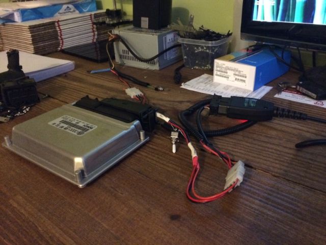
Here is the "finished" product, just needs to be wrapped with some wire-loom tape.

SUCCESS

i hope that this can be helpful to someone else

 Reply With Quote


Bookmarks