============
First, a few things:
*Every version of Ross-Tech software is slightly different. In terms of logging, the only real difference is the location number associated with each logging parameter. The name of the parameter will be similar from version to version, but the associated location number may be different. I am using version 12.12.1 in the screen captures below, but I have updated it with the parameters from version 15.7.1 (updated 10/8/2015). Regardless, your version may be slightly different. The software is updated often.
*One of the key things people like to log is requested and actual boost. In recent versions of the Ross-Tech software boost is not displayed as an absolute value. Some conversion and calculation is required. This is covered in the next post.
*While there are others ways to log a vehicle, this only covers using the full version of Ross-Tech software with their VCDS cable.
*Logging must be done with Windows software. That can be XP, Vista, Windows 7 or 8. Doesn’t really matter. An Apple/Mac that runs Windows will also work (Boot Camp, Parallels, etc.).
============
Getting Started
Step 1: Plug the Ross-Tech VCDS cable into the OBDII port under the dash on the driver’s side.
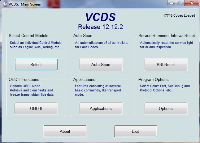
Step 2: With the car on, launch the VCDS software.
*Note: The car can be in the ON position or running for steps 1-11.
Check for Fault Codes
Step 3: Before you start logging, ensure there are no fault codes. Press the “Auto-Scan” button on the VCDS main menu.
Step 4: Once in the Auto-Scan section, press the “Start” button to scan for codes. The scan will take a few minutes as it scans all modules. If there are faults, I would recommend saving the scan results (copy/paste, save, print), and then clear the faults with the “Clear all DTC’s” button. Once this is done, “Close” the Auto-Scan section, and return to the main menu.

Logging Setup
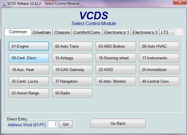
Step 5: Under “Select Control Module” press the “Select” button.

Step 6: Under the “Common” tab press the “01-Engine” module button.
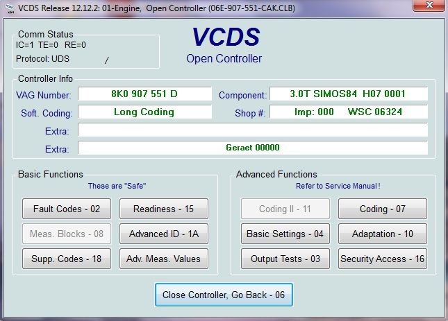
Step 7: In the Engine Controller module, press the “Adv. Meas. Values” button to access the logging section.
Step 8: Select the “Ambient Air Pressure” value from the parameter list. Record the value displayed for future reference, and then uncheck the box. The ambient pressure value will be used later to calculate boost related values.
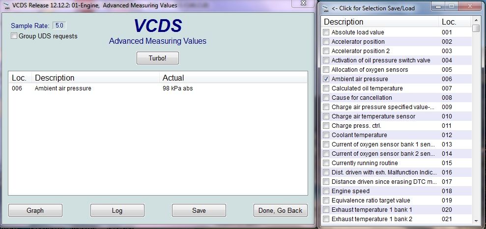
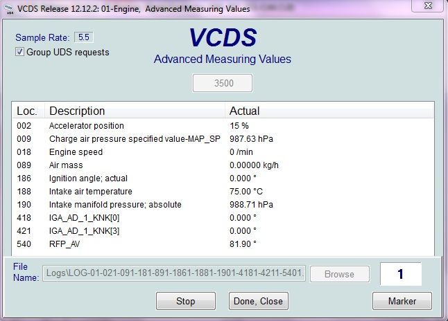
Step 9: Select the parameters you would like to log from the list.
*Notes:
-VCDS will let you select a maximum of 12 parameters, or 10 parameters if you use grouping (which is a must for good logs as we’ll cover below). So, concentrate on the parameters that are most important for this particular logging session. Fewer parameters logged will yield higher resolution logs.
-For general performance logging, I recommend the following parameters, but you can pick the appropriate parameter for your needs from the list:
For B8:
Group Number: Parameter Field (Units; details)
002: Accelerator position (in %)
009: Charge air pressure specified value (in hPa; specified boost+ambient air pressure)
018: Engine speed (in RPM)
089: Air mass (in kg/h; intake)
186: Ignition angle; actual (in degrees)
188: Intake air temperature (in degrees C)
190: Intake manifold pressure; absolute (in hPa; actual boost+ambient air pressure)
418: IGA_AD_KNK[0] (in degrees; knock detection/timing pulled on cylinder 1- Just pick 2 Cylinders to log)
419: IGA_AD_KNK[1] (in degrees; knock detection/timing pulled on cylinder 2- Just pick 2 Cylinders to log)
420: IGA_AD_KNK[2] (in degrees; knock detection/timing pulled on cylinder 3- Just pick 2 Cylinders to log)
421: IGA_AD_KNK[3] (in degrees; knock detection/timing pulled on cylinder 4- Just pick 2 Cylinders to log)
422: IGA_AD_KNK[4] (in degrees; knock detection/timing pulled on cylinder 5- Just pick 2 Cylinders to log)
423: IGA_AD_KNK[5] (in degrees; knock detection/timing pulled on cylinder 6- Just pick 2 Cylinders to log)
540: RFP_AV (bypass valve %)
For B8.5:
Group Number: Parameter Field (Units; details)
Group 2: Accelerator position (%)
Group 11: Charge air pressure specified value (hPa)
Group 24: Engine speed (rpm)
Group 134: Air mass (kg/h)
Group 226: Ignition angle; actual (degrees)
Group 228: Intake air temperature (in degrees C)
Group 230: Intake manifold pressure; absolute (hPa)
Group 480-485: IGA_AD_1_KNK_x (knock correction in degrees; x is cylinder number 0-5)
Group 616: RFP_AV (bypass valve %)
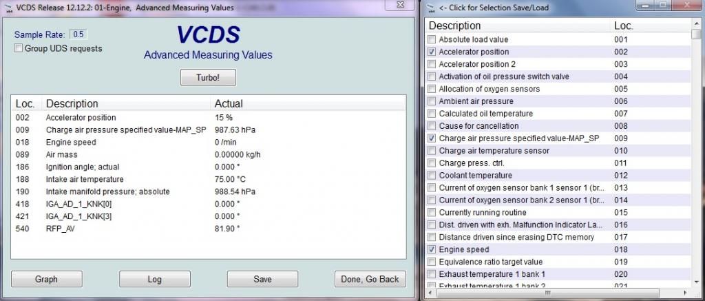
Step 10: Save the parameter list so you can easily access it at a later time by clicking the "VCDS" icon in the top-left corner. Name the file “performance” or similar. If you have parameter files for other types of logging, name them appropriately.
Logging
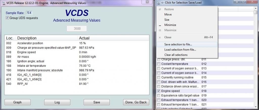
Step 11: This step is very important for capturing good logs. Press the “Turbo” button, and check the “Group UDS requests” box at the top of the screen. This will speed up the logging, and also group all 10 fields to the same timestamp. This is the only way to get useful logs (otherwise, each parameter will have a different timestamp).
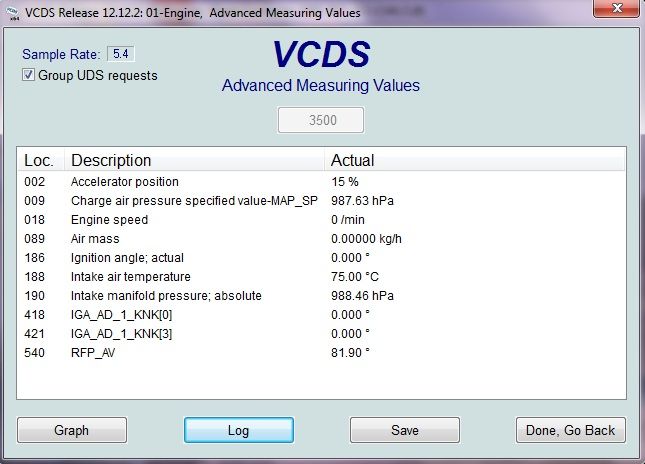
Step 12: Press the “Log” button to initiate the logging session. This will not start the actual logging process
*Note: Your car should be running if it is not already.
Step 13: When you are ready, press the “Start” button. This will start the actual logging process.
*Notes:
-Logging should be performed in a controlled area where you can safely reach 85-90 MPH. The drag strip or dyno are the best options, but in places like Texas there are some pretty safe places to do this on the road (I do it late at night in traffic free areas with 70+ MPH speed limits).
-Logging runs should capture a full 3rd gear pull at a minimum. 4th is probably a little better, but that should only be done at the drag strip or on a dyno. A full pull is around 3000 RPM to 7000 RPM. This can be tricky on a DSG car because you need to avoid triggering the kickdown switch at lower RPM’s. Play around with what works best, but the sooner you can get to full acceleration the better.
-When logging, the A/C and radio should be OFF, the windows UP, car IN dynamic mode if available, and traction/ASR OFF (hold traction button for at least 5 seconds to turn both off).
-Logging should be done on a flat surface, and if done multiple times it should be done at the same location and in similar conditions if possible. This makes comparing data more accurate.
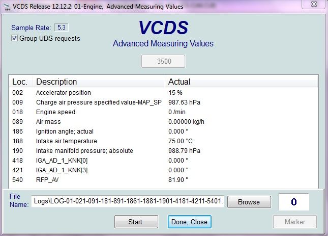
Step 14: Once you have captured the needed logs, press the “Stop” button to stop the logging process, and “Done, close” when finished. The logs will be saved to the Ross-Tech/VCDS/Logs folder as a .CSV file (typically on the C:/ or wherever the Ross-Tech software is installed). It can be opened with Excel or similar.
============
That is it for capturing basic performance logs. The next post will cover some of the basics in regards to interpreting the logs.
============
In addition to logging the basic performance parameters listed above, VCDS gives the option to log many many other things.
*Some examples:
-If you are experiencing timing being pulled due to engine knock detection, you may want to log knock on each individual cylinder instead of just the 2 covered above. In that case you would want to log something like: accelerator position, engine speed, ignition angle; actual, and IGA_AD_KNK[x] on all 6 cylinders. Those 9 parameters may point to an issue with a specific cylinder.
-As you can see, accelerator position and engine speed are really needed every time so you have some reference point in the logs. Intake air temperature is also good to log as it will give a good idea on the conditions.
-More fields and examples are below (updated below).
====================
Update with additional fields:
Misfires:
If you are experiencing misfires, you may want to log misfires on all 6 cylinders to see where the problem is coming from. In that case you would want to log accelerator position, engine speed, misfires all cylinders, misfires cylinder X on all 6 cylinders. These 9 parameters may point to an issue with a specific cylinder, or a more general problem.
Some (low number of) random misfires that DO NOT result in a fault code are fairly normal. I see it on most 3.0 TFSI engines stock or tuned. With that said, Audi has dumbed down the misfire reporting threshold, so it is possible misfires could be causing a performance issue, but also not trigger a CEL. I don't have an answer on what constitutes a real problem.... Maybe others can chime in. In the most basic sense, if you see a CEL due to misfires, there is definitely an issue. If you see a low number of misfires and no CEL, it may be normal. If you see a high number of constant misfires, but no CEL, blame Audi for dumbing down the threshold and try to figure out the problem.
251- Misfires all cylinders per 1000 rpm 0
253- Misfires cylinder 1 per 1000 rpm 0
255- Misfires cylinder 2 per 1000 rpm 0
257- Misfires cylinder 3 per 1000 rpm 0
259- Misfires cylinder 4 per 1000 rpm 0
261- Misfires cylinder 5 per 1000 rpm 0
263- Misfires cylinder 6 per 1000 rpm 0
Lambda/Air:Fuel/EGT:
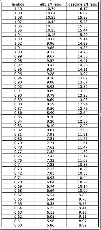
Lambda or Air:Fuel ratio is important to understand for a couple of reasons. The most basic is to ensure your engine tuning is optimal. This is obviously more important with aftermarket (non-OEM) tuning. If you want to see what "normal" is, log your car with the stock tune, and the specified values will give you a pretty good idea for different scenarios. Assuming fueling is sufficient, specific and actual should be fairly close. If the actual number is higher than the specified value, you will start running into issues (not good).
On that note, if you are running E85 or the fuel system near maximum capacity, it is a good way to determine if fueling needs are being met. Again, E85 or if you are mixing E85 with regular gas, could present an issue on the stock fuel system. E85 has (about 33%) less energy per part compared to regular high octane fuel, so it takes roughly 33% more of it to run your vehicle. This can tap out the stock fuel system pretty quickly if too much is used. To run strait E85, and upgraded HPFP would be required. The advantage of E85 is the higher relative octane (close to the equivalent of 105 octane).
020- Exhaust temperature 1 bank 1 460.0 ∞C
021- Exhaust temperature 1 bank 2 459.5 ∞C
238- Lambda probes actual; bank1 0.9971
13- same?
239- Lambda probes actual; bank2 1.0049
14- same?
244- Lambda probes specification; bank 1 0.9971
245- Lambda probes specification; bank 2 0.9971
246- Lambda probes specified; bank1 0.9971
247- Lambda probes specified; bank2 0.9971
(note that 244-247 seem to be the same thing, the specified Lambda value, so logging one is likely sufficient).
194-199: Knock sensor voltage
Table to convert Lambda to Air:Fuel ratios:
Fuel Pressures, Trims, and Injectors
87- Rail pressure actual
170- Rail pressure specified
22- Fuel pressure
187- Fuel pump, actual fuel pressure
Fuel Trims/Adaptations (%)
47- Long-term adaptation; bank 1
48- Long-term adaptation; bank 2
63- Short-term adaptation; bank 1
64- Short-term adaptation; bank 2
Injector Pulse Width (IPW in ms):
609- TI_1_HOM[0]
610- TI_1_HOM[1]
611- TI_1_HOM[2]
612- TI_1_HOM[3]
613- TI_1_HOM[4]
614- TI_1_HOM[5]
To calculate the injector duty cycle, it is something like: (RPM x IPW)/300=IDC
================
Just a quick update on the new version of VCDS (15.7.4). Several people have reported very low resolution when logging 10 parameters with Grouping/Turbo enabled. In my case, I was only getting a couple lines of data on an entire 1/4-mile pass.
Another member changed some settings as recommended by Ross-Tech, and it seemed to help. I've posted the changes he made below. If you are having issues with 15.7.4, you may want to try these changes.


 Reply With Quote


 but thanks again for taking the time to make this guide


 B8.5 Estoril Blue S4 | P+ | DSG | SD | ADS | B&O | CF | Nappa | Advance Key | CF Badges


Bookmarks