There is a PDF version and Power Point Presentation you can download if you want, that resembles this write up. Hopefully this will be helpful!
2001 Audi A6 Turn Signal Fix

BACKGROUND:
While driving to lunch one day I found that my blinkers suddenly stopped blinking and went solid. I confirmed this by getting out of the car and looking at the blinkers when engaged. They were solid for both left and right. I found a circuit diagram and found the flasher relay is integral to the hazard switch. Like so many of you do, I searched the forums and youtube for a fix. I confirmed the relay is in the hazard switch. After a few days of using the blinker switch manually to make the them blink, I suddenly found the blinkers quit coming on all together. CRAP! I thought maybe I broke the multifunction switch, but after “tapping” the dash a few times, the lights came back on solid. The blinker relay has died altogether. I found a “how to” on removing the hazard switch (too easy) and a video on how to disassemble the switch. The video was older version, and the relays were not encased. Mine are encased. I looked up how much a hazard switch would cost and found them to be from $25 (ebay) to $46 from various online stores. Being a “Do-it-Yourselfer” I decided to see if I could fix my hazard switch for cheaper, rather than buy a new one.
After it was all said and done I had spent $10.30 plus shipping, and the blinkers worked as designed.
DISCLAIMER: PERFORM THIS FIX AT YOUR OWN RISK. I AM NOT RESPOSIBLE IF YOU RUIN YOUR SWITCH (or car) PERMANENTLY. This was a fairly simple fix for me, but I do have some circuit board repair experience. I am not an expert at soldering, but I am not a beginner by any means. I also have an above average (self-proclaimed) understanding of wiring diagrams and circuits.
----------
First you need to remove the red lens. One side is larger than the other, you can use a small screwdriver or a pick to pop the tabs on each side.

----------
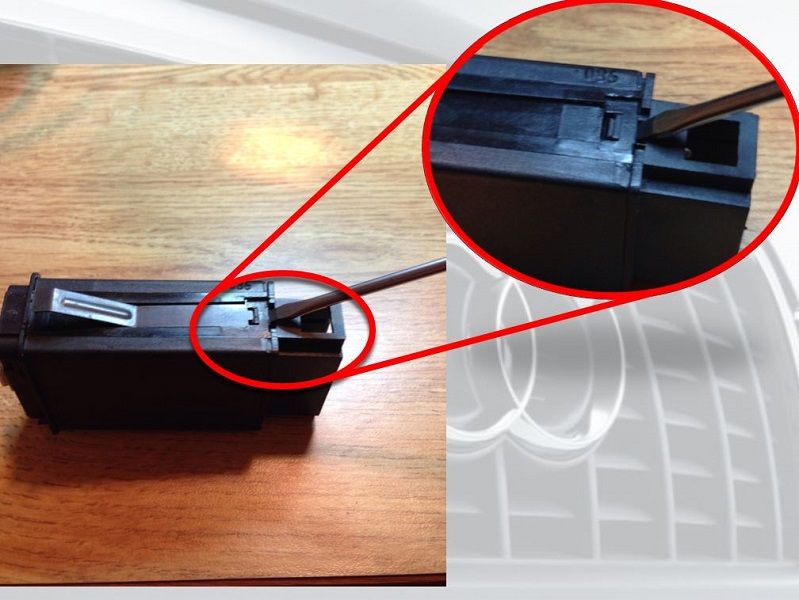
After red lens is removed, use a screwdriver to pop the tab shown, and repeat on the opposite side. Be careful not to break the tabs, they are very thin.

----------

----------
Remove the lock bar that holds the connector casing on the pins. Use a small screwdriver or pick to push through. You may be able to pull through at this point.

----------
The bar was in too tight for me to remove in the last step, so I inserted the screwdriver in the center and pushed it through.

----------

----------
The circled relay is the turn signal flasher relay. It was encased like the one next to it, but I removed all the casing to check for corrosion. There was none so the relay just went bad. The casing was marked Omron G8N-1, after a little “Googling” I found that www.mouser.com sells a G8N-1. I ordered the relay with the hope that it would be the correct one. It cost $10.30 before shipping.
Until it arrives I decided to remove the relay and use a solid piece of wire to allow me to manually make the blinkers flash.
The other, bigger relay is the hazard flasher relay.

----------
Omron G8N-1
Another view of the bad relay.

----------
Hazard Switch Pin Out

----------
Hazard Switch Wiring Diagram (the quality is much better in the PDF version)

----------
These 5 soldered points are the turn signal relay contacts. If you want to remove the relay you will have to heat these point up and de-solder them. The yellow numbers reflect where the connector pins are soldered to the board.

----------
Point A is the power input from the ACC +, point B is the power output when the relay is energized. These are the 2 points that I soldered a piece of solid wire between to allow power to be at the turn signal switch all the time.
***NOTE*** I did this because my relay was completely dead. If your relay is latching but not blinking this is not necessary for you. I do not recommend keeping this setup for an extended period of time. I don’t know the integrity of the piece of wire I used. Also using your blinker switch manually for a long period of time may cause premature failure of the multifunction switch .

----------
I soldered a piece solid wire between the 2 points to allow this circuit to be powered all the time. This allows me to use the turn signal switch to manually make the turn signals blink. This was a temporary fix until I receive my new relay.
***NOTE*** I did this because my relay was completely dead. If your relay is latching, but not blinking, this is not necessary for you. I do not recommend keeping this setup for an extended period of time. I don’t know the integrity of the piece of wire I used. Also using your blinker switch manually for a long period of time may cause premature failure of the multifunction switch .

----------
I ordered this relay from http://www.mouser.com/.

----------
As soon as the new relay arrived I removed the solid piece of wire and prepared for the new relay.

----------
Solder the new relay. Make sure all 5 points have good contact.

----------
At this point you are done. Re-assemble and try it out.


 Reply With Quote


Bookmarks