Audizine - An Automotive Enthusiast Community

Results 1 to 16 of 16
  1. #1
    Veteran Member Four Rings BaseDrifter's Avatar
    Join Date
    May 18 2010
    AZ Member #
    59183
    Location
    Bay Area, CA

    A4 B5 DIY: Install headlight relays

    Guest-only advertisement. Register or Log In now!
    Audi has done a lot of great work and a lot of us love our B5s. Unfortunately Audi's design of the B5 headlight switch was not so stellar.

    No relays were used and the full current draw of both headlights passes through the small plastic contact of the headlight switch. Over time this can cause the plastic to heat up and melt, when the contact housing melts it pulls the metal contact away from the switch which results in the loss of both headlights and fog lights.

    The solution is to install the relays that Audi should have from the factory. There are a few threads about installing headlight relays, however most involve installing the relays some place under the hood. This never appealed to me both for aesthetic reasons and for the simplicity of wiring. Instead I chose to install two OEM plugs and relays into the factory relay panel and wire them through the fuse box. I harvested the plugs and relays from a car at a pick n pull for a few dollars.

    It is always a good idea to have an understanding of the circuitry before you start cutting into the factory harness. Make sure you know what wire you are cutting, where it goes, where it comes from, and why you are cutting it. Could you repair this cut if you make a mistake? (Don't clip a wire at the base of the pin, you won't be able to resolder the wire if you made a mistake.)

    The headlight circuit is pretty straight forward.

    We'll pick up the circuit as power flows into the headlight switch from the starter switch.

    1. Switched power from the starter switch enters headlight switch at pin 2 through a yellow/black wire.

    2. When the headlight switch is turned into the on position (2 clicks up) power flows out from pin 8 into a two yellow wires (it will split into four, but we are only concerned with two.)

    3. From the headlight switch power flows into the fuse panel. Fuse 20 (10A) is for the passenger side low beam, fuse 21 (10A) is for the driver's low beam. This is where we will pick up the signal and reroute it to the relays. From here on out we have two circuits, one for each headlight.

    On the passenger's side, the white/yellow wire coming off the other side of the fuse goes directly to the low beam. On the driver's side, it is the black/yellow wire that goes to the low beam.

    We want to keep the stock fuses in place, so we will be tapping into the wires after the fuse, white/yellow and black/yellow. The advantage of splicing into the wires here is that both wires are in the same location. The harness splits further towards the front of the car and you may be having to trace the harness, cut into it, pull wire out...not fun. There is room to work in the fuse box area.

    Alright now time for some pictures and instruction.

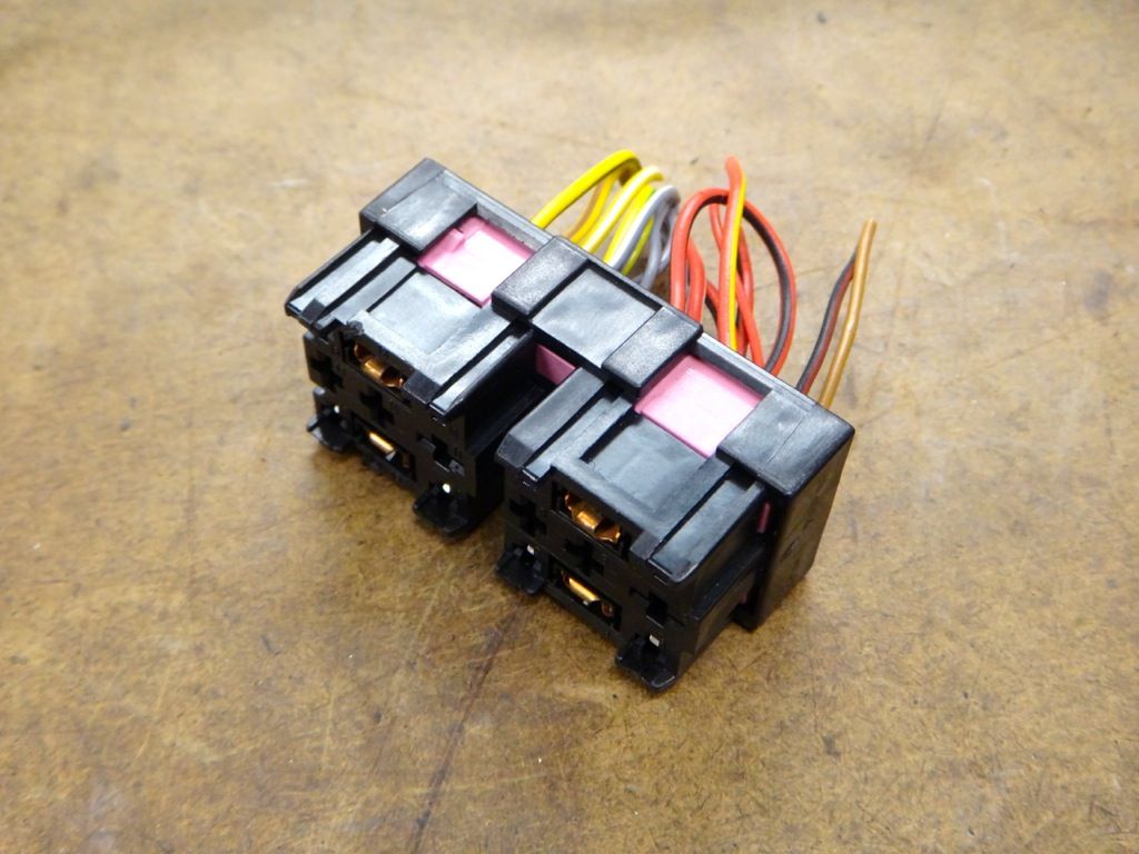
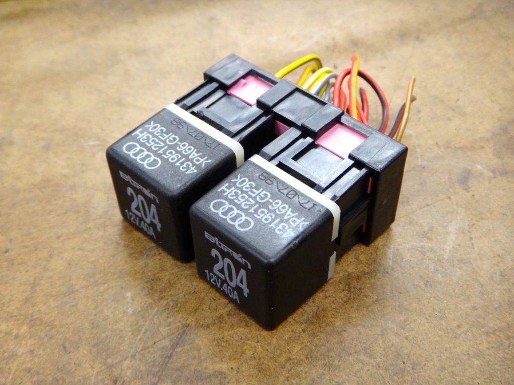
    1. Start by gathering the relays and plugs you will need. While it would be possible to install a single relay for both headlights, it would be wise to keep the circuits separate and run each light off its own relay. I found a nifty double relay plug that works great for this, though there is no reason you can't use two individual plugs.

    Here is the plug I got.


    With relays.
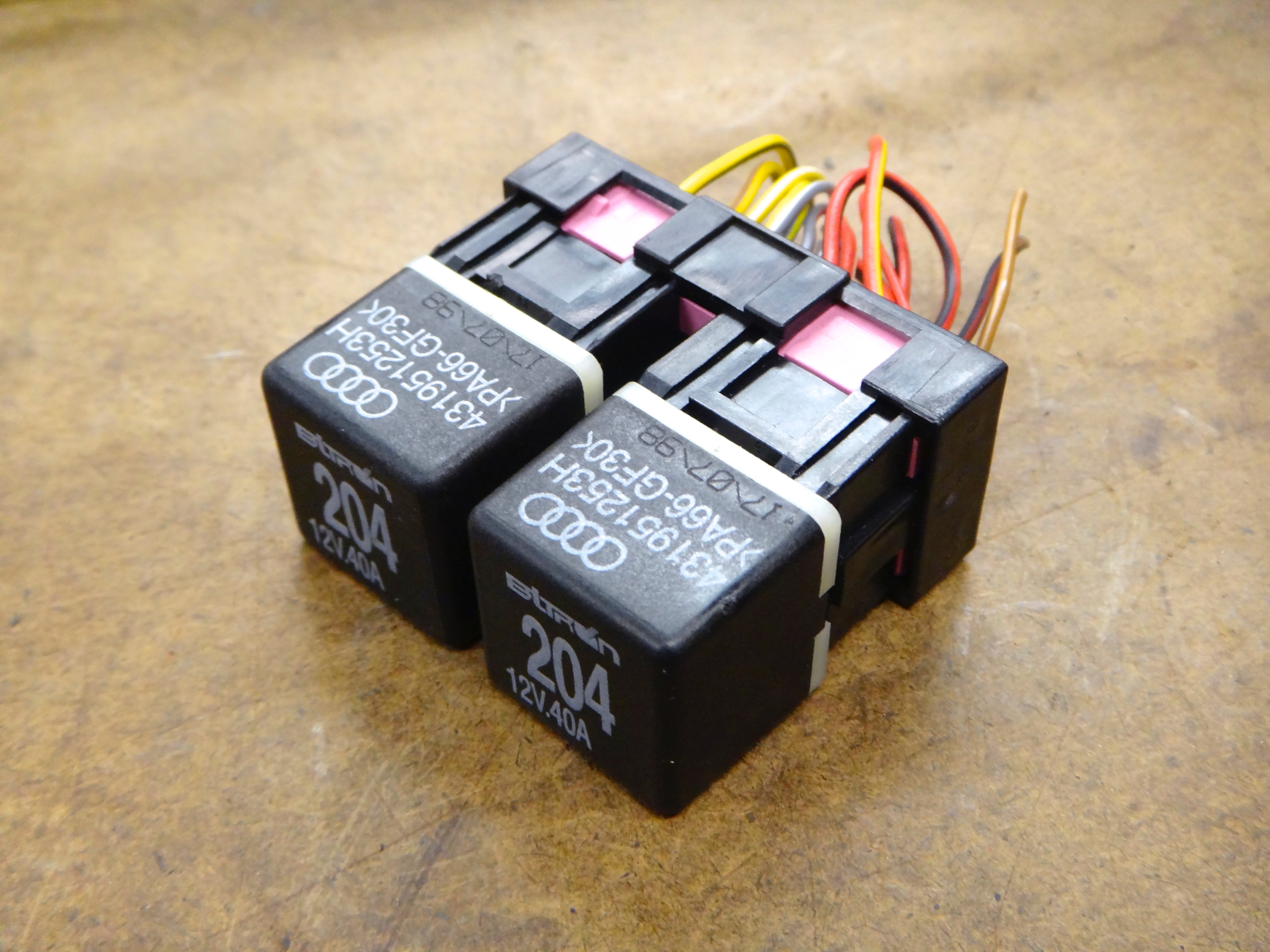


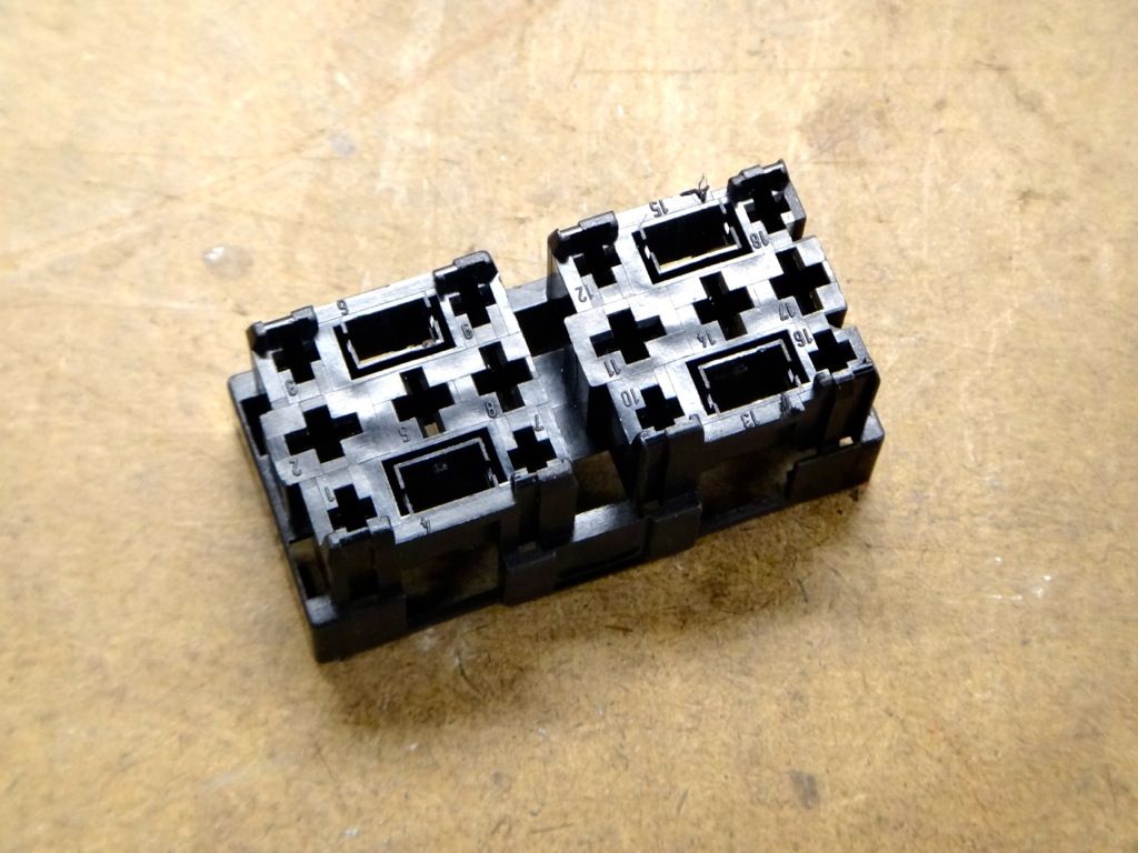
    We will only be using four wires per relay, so we can remove the majority of the pins in the plug. Removing the pins can be a headache. Each pin has two locking tabs on the top and bottom, both must be depressed to pull the pin out. I made two "pokers" out of a piece of flatstock brass. Once you get the hang of it they go easy, you'll be cursing at the first few though.


    Empty plug.


    2. Next you'll want to remove the knee bolster, it is held in place with 3 8mm bolts hidden behind cover panels. Make sure to disconnect the VAG COM hookup before pulling the cover away. Disconnect the floor light if you have one as well.

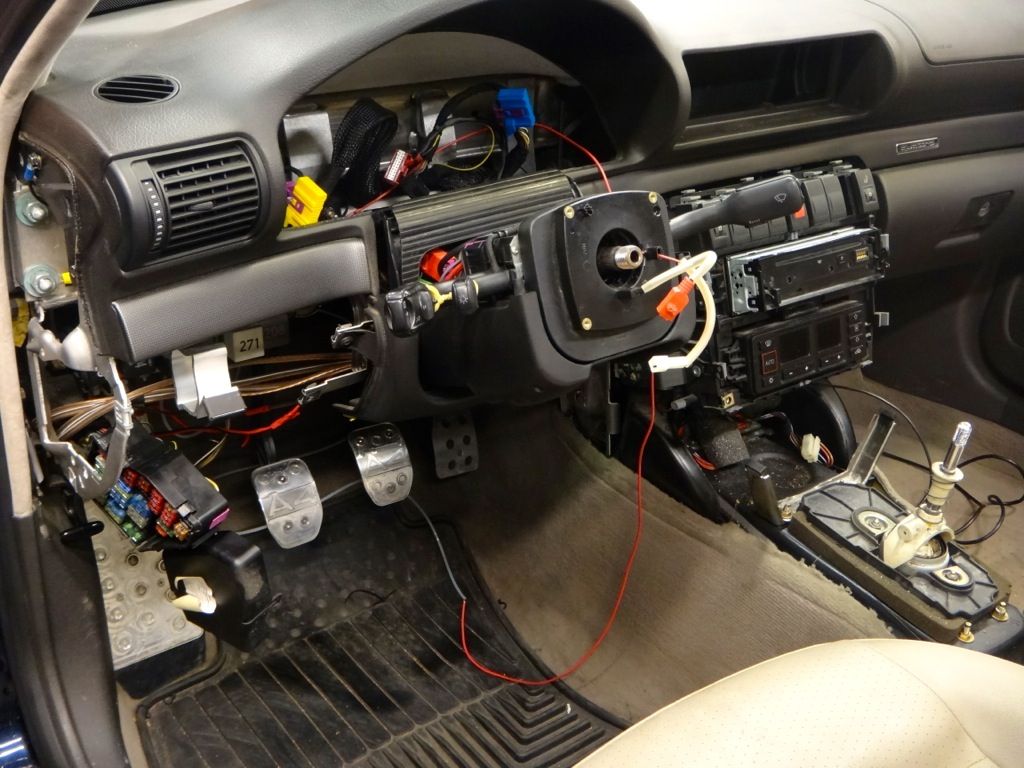
    3. Remove the fuse box from it's cage. It is secured with two 8mm bolts and two clips. Remove the bolts, pop the clips, and work the fusebox downwards until it is clear of the metal frame. Two clips on the side of the fusebox keep it closed, pop those clips open. You'll see the wires we are interested in at the top outermost corner, nice and easy to get to!

    Here you can see the bolster removed and fuse box pulled down. (Don't worry about the missing steering wheel and cluster, those were removed for another project and aren't necessary to remove for this project.)


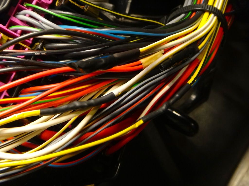
    4. With the fusebox pulled down and the cover popped open you should be able to see the wires we are looking for. Make sure you have the correct wires. One white/yellow and one black/yellow. Cut them about halfway from the fuse to where they enter the harness. Leave enough room to do your soldering.

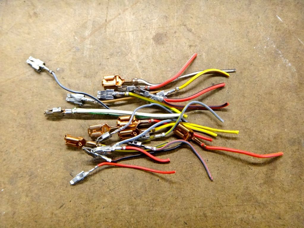
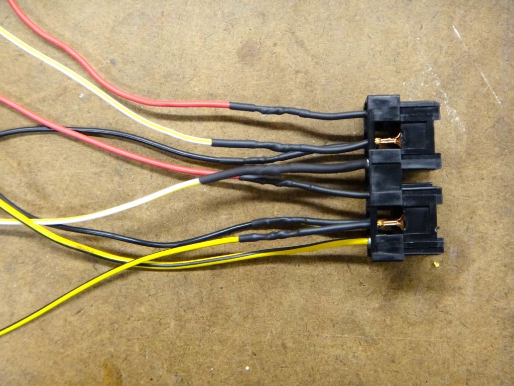
    5. Take some measurements/estimates of length and start wiring up the relay wiring harness. I actually harvested some OEM white/yellow and black/yellow wire from a donor car to complete the wiring harness. Any color of the proper gauge may be used. For cleanliness and ease of problem solving later, sticking to the same color is highly recommended. Use electrical tape on some yellow wire if you can't get OEM wiring.

    Here I have soldered on new wire to the pins for the harness.


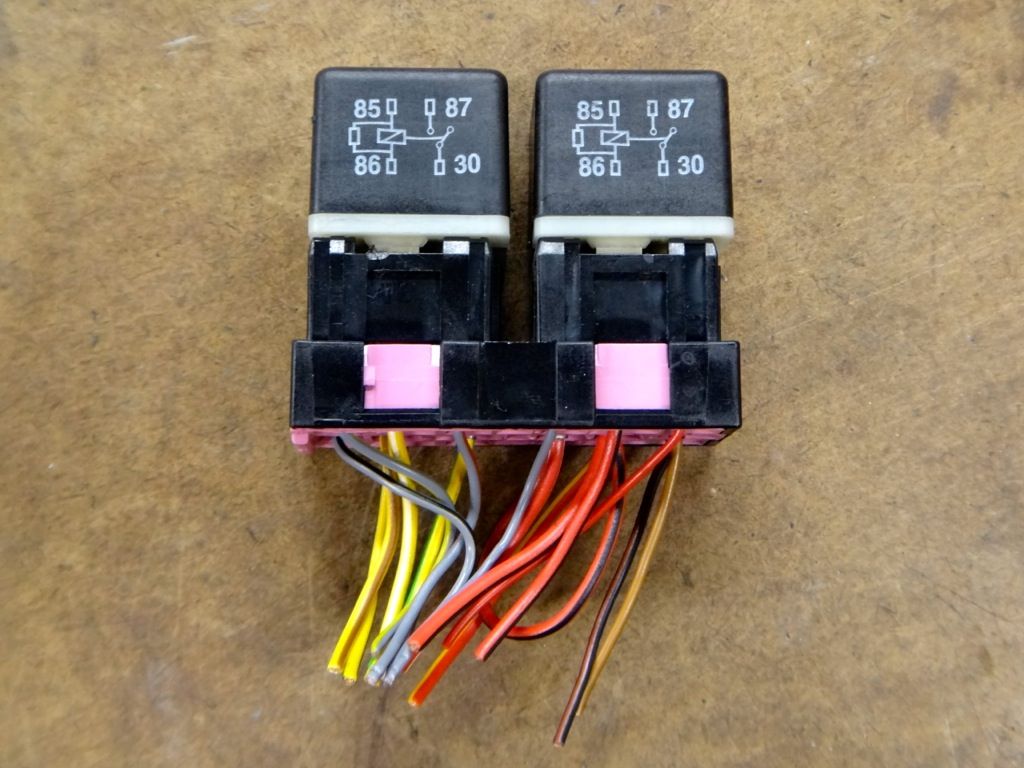
    I guess I should talk about wiring the relay now. The relay has 4 contacts. A signal input, a power input, a power output, and a ground.

    - Pin 85 is the ground.
    - Pin 86 is the signal input
    - Pin 30 is the power input
    - Pin 87 is the power output.

    In our case, we are taking the input from the headlight switch to trigger the relay to send power out to the headlights. So pin 86 receives a signal from the headlight switch to close the contact between pin 30 and pin 87, sending power to the headlight.

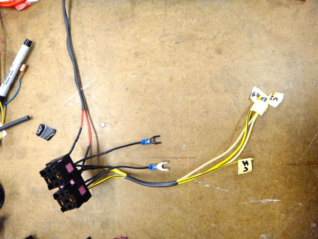
    Here is my finished harness. The two red wires go to a fused power distribution block hooked up to the switched 75x post under the dash. The two black wires are the grounds, and the two yellow/white and two yellow/black wires are the inputs and outputs for each light.


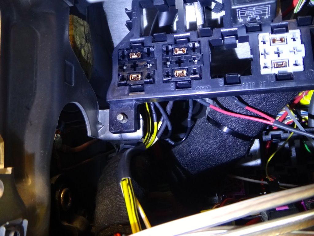
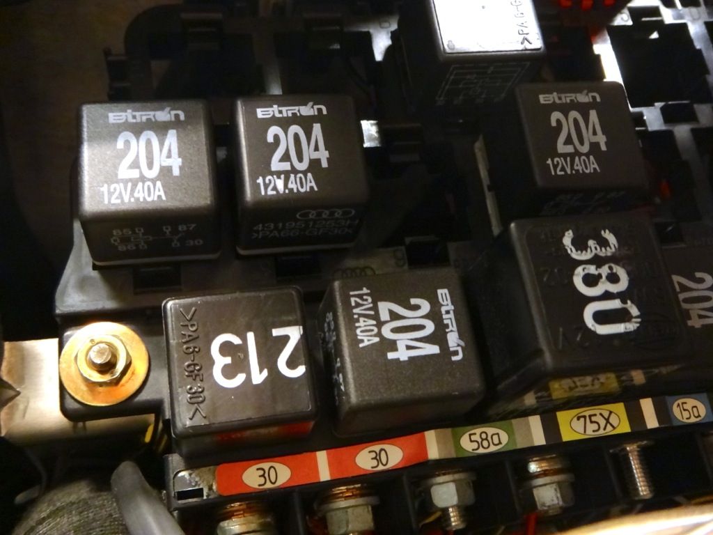
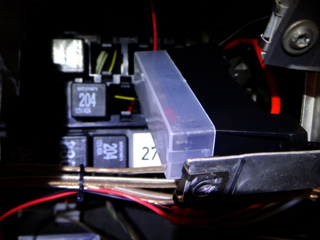
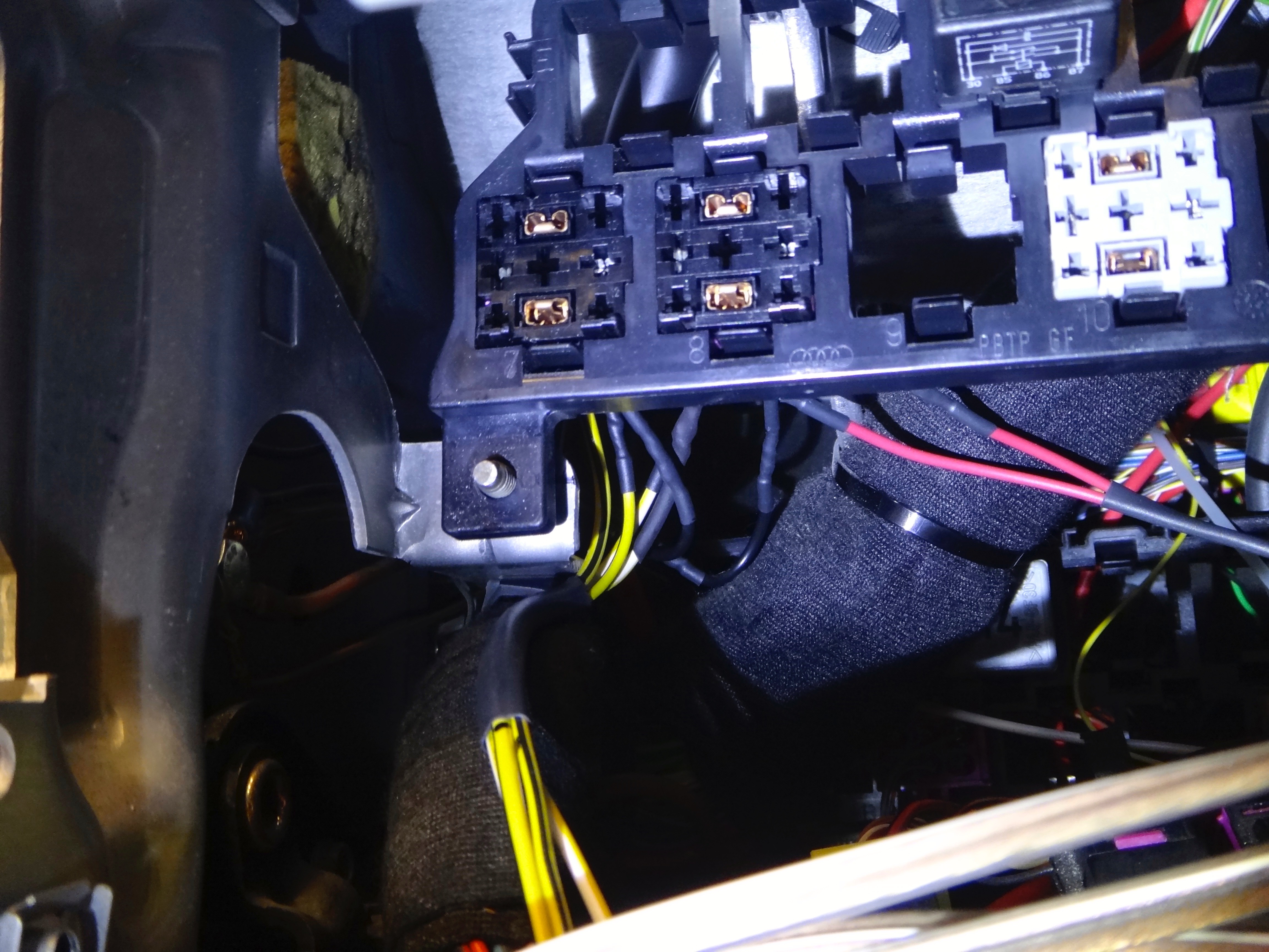
    Here are the plugs installed into the relay panel. I chose the two slots at the left most position since it is closest to the fuse box.


    Relays installed.


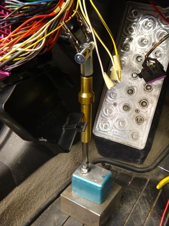
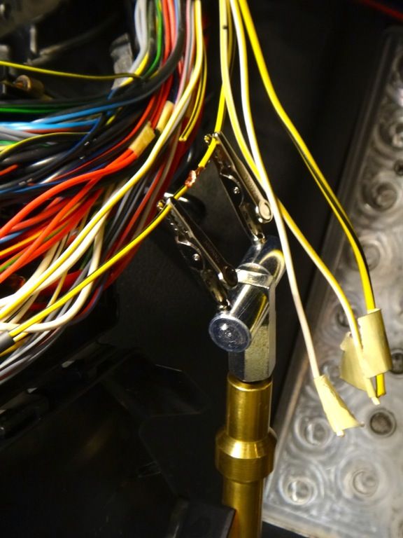
    6. Once you are sure you have the proper wire lengths, you can start to solder the harness in place.


    A little hard to see, but here are the final connections spliced into place.


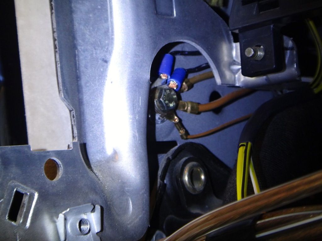
    Directly to the left of the relay panel is a factory grounding location. I ran both relays over to this ground.


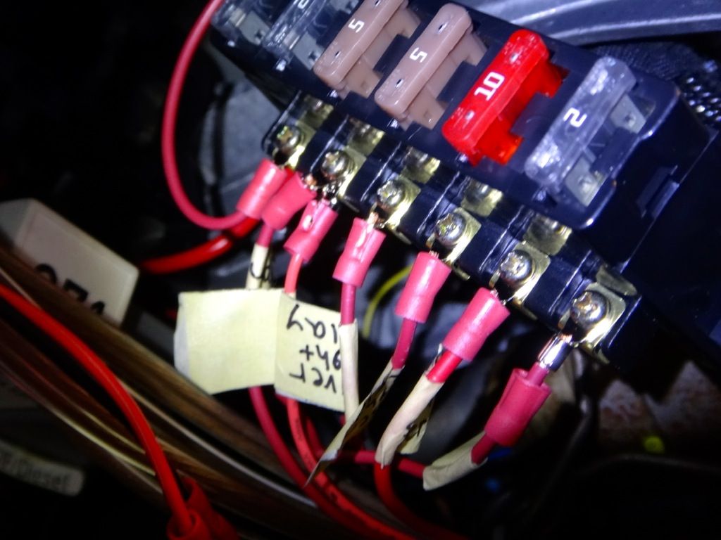
    The last piece of the puzzle is getting a new power supply to the relays. I chose to install a fused power distro block which is secured to the knee bolster frame with zip ties. The block is connected to post 75x so the relays will only receive power if the key is in the on position.

    Here is the block installed.


    The relays are hooked up to 3rd and 4th slots. Both are running through 5amp fuses.


    That's it! You headlights should now be running off the relays and you should never have to worry about melting your headlight switch again. If you are interested in having independent fog lights, this is a splendid time to tackle that project while you have everything apart. (http://www.audizine.com/forum/showth...ent-fog-lights)

    Last edited by BaseDrifter; 12-28-2017 at 09:38 PM.
    | Update thread / Youtube Channel |

    97 A4 1.8TQM: Frankenturbo|TyrolSport SMIC|034 HFC|Borla catback|Carbonio/007 DV|Vogtland GT3|034 RSB|Apikol Bushings|034 SD motor/tranny/strut mounts|A8 brakes/SS lines|JHM trio|Meyle HD CA/TREs|
    01 S4 2.7T: Stock

  2. #2
    Active Member Two Rings
    Join Date
    Dec 10 2011
    AZ Member #
    85091
    Location
    Australia

    awesome tutorial! may tackle this in the near future.
    on a side note..im very interested in that helping-hand contraption you're using to hold the wires..care to share some details? :)

    Sent from my Incredible S S710e using Tapatalk 4

  3. #3
    Veteran Member Three Rings Artiemas's Avatar
    Join Date
    May 30 2012
    AZ Member #
    94375
    Location
    North Branford, CT

    Yours is 10x neater than mine..And soldered. I just have scotch locks and shit. I see you didn't put any inline fuses through. I did on mine, to prevent the relay from blowing, and rather the fuse first.

    Also, you used a external power source, why not just use one of the "30" posts for power?
    1998.5 Cactus Green A4
    30v AHAQM Bone stock

  4. #4
    Veteran Member Four Rings BaseDrifter's Avatar
    Join Date
    May 18 2010
    AZ Member #
    59183
    Location
    Bay Area, CA

    Quote Originally Posted by crunchie View Post
    awesome tutorial! may tackle this in the near future.
    on a side note..im very interested in that helping-hand contraption you're using to hold the wires..care to share some details? :)

    Sent from my Incredible S S710e using Tapatalk 4
    Thanks! It's just a magnetic wire holder for soldering I stuck on top of various other tools to get it to the right height. It makes soldering in midair at least doable with only one person.

    Quote Originally Posted by Artiemas View Post
    Yours is 10x neater than mine..And soldered. I just have scotch locks and shit. I see you didn't put any inline fuses through. I did on mine, to prevent the relay from blowing, and rather the fuse first.

    Also, you used a external power source, why not just use one of the "30" posts for power?
    Haha thanks, neatness was the goal.

    Your post had me rethinking my wiring. The way I have it wired right now the stock headlight fuse is protecting the signal wire from the headlight switch that feeds the relays. The headlights are each fused, albeit behind the relay. Fusing behind the relay still offers circuit protection but doesn't protect the relay from a fault to ground. I could rewire it so that the signal goes directly to the relay and the relay output passes through the stock fuse location, that would seem to make more sense...but I'm not sure if it's worth the trouble now.

    I used the 75x post since it is a switched power source.
    | Update thread / Youtube Channel |

    97 A4 1.8TQM: Frankenturbo|TyrolSport SMIC|034 HFC|Borla catback|Carbonio/007 DV|Vogtland GT3|034 RSB|Apikol Bushings|034 SD motor/tranny/strut mounts|A8 brakes/SS lines|JHM trio|Meyle HD CA/TREs|
    01 S4 2.7T: Stock

  5. #5
    Senior Member Three Rings
    Join Date
    Jan 21 2008
    AZ Member #
    24370
    Location
    Tucson

    Why not splice in the relays right at the headlights?

  6. #6
    Veteran Member Four Rings BaseDrifter's Avatar
    Join Date
    May 18 2010
    AZ Member #
    59183
    Location
    Bay Area, CA

    Quote Originally Posted by mysman View Post
    Why not splice in the relays right at the headlights?
    Reasons not to put the relays at the headlights:

    1. Putting more equipment and wiring in the engine bay is not the direction I want to be going, I want less in the engine bay and more hidden away.

    2. The relays are in different locations which means you can't make up a nice tight wiring harness like I did, you'll be running more wire with the relays near the lights.

    3. It is easier to mount a distro box under the dash where you don't have to worry about moisture or use in-line fuses.

    4. Tapping into the wires at the fuse box means you don't have to cut open the harness further up the line, the wires are easily accessible under the dash.
    | Update thread / Youtube Channel |

    97 A4 1.8TQM: Frankenturbo|TyrolSport SMIC|034 HFC|Borla catback|Carbonio/007 DV|Vogtland GT3|034 RSB|Apikol Bushings|034 SD motor/tranny/strut mounts|A8 brakes/SS lines|JHM trio|Meyle HD CA/TREs|
    01 S4 2.7T: Stock

  7. #7
    Senior Member Three Rings
    Join Date
    Jan 21 2008
    AZ Member #
    24370
    Location
    Tucson

    Quote Originally Posted by lm0812 View Post
    Reasons not to put the relays at the headlights:

    1. Putting more equipment and wiring in the engine bay is not the direction I want to be going, I want less in the engine bay and more hidden away.

    2. The relays are in different locations which means you can't make up a nice tight wiring harness like I did, you'll be running more wire with the relays near the lights.

    3. It is easier to mount a distro box under the dash where you don't have to worry about moisture or use in-line fuses.

    4. Tapping into the wires at the fuse box means you don't have to cut open the harness further up the line, the wires are easily accessible under the dash.
    Agree with some of that, but the stock headlight wiring is undersized. With point of use relays you are able improve this situation.

  8. #8
    Active Member One Ring Ninja546's Avatar
    Join Date
    Jul 20 2013
    AZ Member #
    119318
    Location
    Idaho

    Quote Originally Posted by lm0812 View Post
    Audi has done a lot of great work and a lot of us love our B5s. Unfortunately Audi's design of the B5 headlight switch was not so stellar.

    No relays were used and the full current draw of both headlights passes through the small plastic contact of the headlight switch. Over time this can cause the plastic to heat up and melt, when the contact housing melts it pulls the metal contact away from the switch which results in the loss of both headlights and fog lights.

    The solution is to install the relays that Audi should have from the factory. There are a few threads about installing headlight relays, however most involve installing the relays some place under the hood. This never appealed to me both for aesthetic reasons and for the simplicity of wiring. Instead I chose to install two OEM plugs and relays into the factory relay panel and wire them through the fuse box. I harvested the plugs and relays from a car at a pick n pull for a few dollars.

    It is always a good idea to have an understanding of the circuitry before you start cutting into the factory harness. Make sure you know what wire you are cutting, where it goes, where it comes from, and why you are cutting it. Could you repair this cut if you make a mistake? (Don't clip a wire at the base of the pin, you won't be able to resolder the wire if you made a mistake.)

    The headlight circuit is pretty straight forward.

    We'll pick up the circuit as power flows into the headlight switch from the starter switch.

    1. Switched power from the starter switch enters headlight switch at pin 2 through a yellow/black wire.

    2. When the headlight switch is turned into the on position (2 clicks up) power flows out from pin 8 into a two yellow wires (it will split into four, but we are only concerned with two.)

    3. From the headlight switch power flows into the fuse panel. Fuse 20 (10A) is for the passenger side low beam, fuse 21 (10A) is for the driver's low beam. This is where we will pick up the signal and reroute it to the relays. From here on out we have two circuits, one for each headlight.

    On the passenger's side, the white/yellow wire coming off the other side of the fuse goes directly to the low beam. On the driver's side, it is the black/yellow wire that goes to the low beam.

    We want to keep the stock fuses in place, so we will be tapping into the wires after the fuse, white/yellow and black/yellow. The advantage of splicing into the wires here is that both wires are in the same location. The harness splits further towards the front of the car and you may be having to trace the harness, cut into it, pull wire out...not fun. There is room to work in the fuse box area.

    Alright now time for some pictures and instruction.

    1. Start by gathering the relays and plugs you will need. While it would be possible to install a single relay for both headlights, it would be wise to keep the circuits separate and run each light off its own relay. I found a nifty double relay plug that works great for this, though there is no reason you can't use two individual plugs.

    Here is the plug I got.


    With relays.


    We will only be using four wires per relay, so we can remove the majority of the pins in the plug. Removing the pins can be a headache. Each pin has two locking tabs on the top and bottom, both must be depressed to pull the pin out. I made two "pokers" out of a piece of flatstock brass. Once you get the hang of it they go easy, you'll be cursing at the first few though.


    Empty plug.


    2. Next you'll want to remove the knee bolster, it is held in place with 3 8mm bolts hidden behind cover panels. Make sure to disconnect the VAG COM hookup before pulling the cover away. Disconnect the floor light if you have one as well.

    3. Remove the fuse box from it's cage. It is secured with two 8mm bolts and two clips. Remove the bolts, pop the clips, and work the fusebox downwards until it is clear of the metal frame. Two clips on the side of the fusebox keep it closed, pop those clips open. You'll see the wires we are interested in at the top outermost corner, nice and easy to get to!

    Here you can see the bolster removed and fuse box pulled down. (Don't worry about the missing steering wheel and cluster, those were removed for another project and aren't necessary to remove for this project.)


    4. With the fusebox pulled down and the cover popped open you should be able to see the wires we are looking for. Make sure you have the correct wires. One white/yellow and one black/yellow. Cut them about halfway from the fuse to where they enter the harness. Leave enough room to do your soldering.

    5. Take some measurements/estimates of length and start wiring up the relay wiring harness. I actually harvested some OEM white/yellow and black/yellow wire from a donor car to complete the wiring harness. Any color of the proper gauge may be used. For cleanliness and ease of problem solving later, sticking to the same color is highly recommended. Use electrical tape on some yellow wire if you can't get OEM wiring.

    Here I have soldered on new wire to the pins for the harness.


    I guess I should talk about wiring the relay now. The relay has 4 contacts. A signal input, a power input, a power output, and a ground.

    - Pin 85 is the ground.
    - Pin 86 is the signal input
    - Pin 30 is the power input
    - Pin 87 is the power output.

    In our case, we are taking the input from the headlight switch to trigger the relay to send power out to the headlights. So pin 86 receives a signal from the headlight switch to close the contact between pin 30 and pin 87, sending power to the headlight.

    Here is my finished harness. The two red wires go to a fused power distribution block hooked up to the switched 75x post under the dash. The two black wires are the grounds, and the two yellow/white and two yellow/black wires are the inputs and outputs for each light.


    Here are the plugs installed into the relay panel. I chose the two slots at the left most position since it is closest to the fuse box.


    Relays installed.


    6. Once you are sure you have the proper wire lengths, you can start to solder the harness in place.


    A little hard to see, but here are the final connections spliced into place.


    Directly to the left of the relay panel is a factory grounding location. I ran both relays over to this ground.


    The last piece of the puzzle is getting a new power supply to the relays. I chose to install a fused power distro block which is secured to the knee bolster frame with zip ties. The block is connected to post 75x so the relays will only receive power if the key is in the on position.

    Here is the block installed.


    The relays are hooked up to 3rd and 4th slots. Both are running through 5amp fuses.


    That's it! You headlights should now be running off the relays and you should never have to worry about melting your headlight switch again. If you are interested in having independent fog lights, this is a splendid time to tackle that project while you have everything apart. (http://www.audizine.com/forum/showth...ent-fog-lights)


    Great Tutorial,

    Though, You started with the switch (assembly) yet there are no pics or any kind of diagrams.. I mean there are alot of wires coming out of that switch. No pics?
    For example Pin 8. What Pin 8, where is that Pin 8 at? Know what I mean.. I trying to visualize the flow. Not to mention.. I worked on many cars.. Just not ready tear my whole dash down.


    I need to focus at the main issue, where is that brake up at the switch. What is exactly happening "Two clicks UP". If I find the pin 8, from PIN 8 where does it go?
    I want to be able to visualize the flow.. That path.

    Thanks

  9. #9
    Veteran Member Four Rings BaseDrifter's Avatar
    Join Date
    May 18 2010
    AZ Member #
    59183
    Location
    Bay Area, CA

    Thanks, as I posted over on AF, I didn't post any diagrams since I don't feel right copying and posting a Bentley diagram, can't say I'm great at drawing wiring diagrams myself either. I will always recommend that people buy a Bentley manual if you plan to do any work to your B5. It is an invaluable resource. I spent many many hours pouring over the electrical diagrams to figure this out.

    If you look on the back of the headlight switch all the pins are marked with their numbers. Pin 8 will have two yellow wires coming off it which lead down to the fuse box where the splicing should be done.

    If you need more clarification on the process don't hesitate to ask.

    PS: When replying to a really long thread like this, it's best not to quote the entire post. :)
    | Update thread / Youtube Channel |

    97 A4 1.8TQM: Frankenturbo|TyrolSport SMIC|034 HFC|Borla catback|Carbonio/007 DV|Vogtland GT3|034 RSB|Apikol Bushings|034 SD motor/tranny/strut mounts|A8 brakes/SS lines|JHM trio|Meyle HD CA/TREs|
    01 S4 2.7T: Stock

  10. #10
    Registered Member One Ring
    Join Date
    Dec 12 2016
    AZ Member #
    388113
    Location
    Alicante

    Hey, first of all thanks a lot for this DIY. I am having exactly these problems that from time to time my low beam-light goes off and i hope to improve it the same way you did. If not, i will also have to replace the switch.
    I have some questions regarding this:
    - What is the reason to use two relays if the full current of both lights in the factory setting goes anyway through the light-switch in one circuit? Afaik one Relays with 40A/12V should be by far enough to power two 55W bulbs.
    - Would it be possible to use the second relays then for another purpose like doing the same for the full-beam lights? Do you by chance know the color coming from the steering wheel switches for those?
    - Last one: Does the sound still work, when one forgot to switch off the lights?

    Thanks a lot for any hints/suggestions and excuse me if something was lost in translation, normally not doing a lot of car-specific english ;-))

  11. #11
    Senior Member Two Rings
    Join Date
    Apr 02 2013
    AZ Member #
    112550
    Location
    above top secret

    Quote Originally Posted by Thrakath View Post
    Hey, first of all thanks a lot for this DIY. I am having exactly these problems that from time to time my low beam-light goes off and i hope to improve it the same way you did. If not, i will also have to replace the switch.
    I have some questions regarding this:
    - What is the reason to use two relays if the full current of both lights in the factory setting goes anyway through the light-switch in one circuit? Afaik one Relays with 40A/12V should be by far enough to power two 55W bulbs.
    - Would it be possible to use the second relays then for another purpose like doing the same for the full-beam lights? Do you by chance know the color coming from the steering wheel switches for those?
    - Last one: Does the sound still work, when one forgot to switch off the lights?

    Thanks a lot for any hints/suggestions and excuse me if something was lost in translation, normally not doing a lot of car-specific english ;-))
    1) I did the modification with only one 30A relay, except that I tapped the power source from post 30 (constant 12V) instead of the switched 75x to avoid overloading the 75x relay. But I used 12 awg wire from the power source to the relay, and two (2) 14 awg wires from the relay to each headlight input wire.
    2) Yes you can. Wire color may be different for different countries. Best to refer to the fuse diagram and check with a voltmeter. I didn't do this mod because the hi beam is not regularly used.
    3) Yes because it is tied to the 6W city light in my car (UK spec). The main beam will switch off once the key is taken out.
    Last edited by maxiz1; 12-15-2016 at 12:17 AM.

  12. #12
    Registered Member One Ring
    Join Date
    Dec 12 2016
    AZ Member #
    388113
    Location
    Alicante

    Hey will have time for this mod soon, but the picture seems to have dissappeared. Can you re-upload them or share by dropbox or sth else?

  13. #13
    Veteran Member Four Rings BaseDrifter's Avatar
    Join Date
    May 18 2010
    AZ Member #
    59183
    Location
    Bay Area, CA

    Just updated all of the old dead links, pictures are back online now.
    | Update thread / Youtube Channel |

    97 A4 1.8TQM: Frankenturbo|TyrolSport SMIC|034 HFC|Borla catback|Carbonio/007 DV|Vogtland GT3|034 RSB|Apikol Bushings|034 SD motor/tranny/strut mounts|A8 brakes/SS lines|JHM trio|Meyle HD CA/TREs|
    01 S4 2.7T: Stock

  14. #14
    Veteran Member Four Rings walky_talky20's Avatar
    Join Date
    Jun 30 2008
    AZ Member #
    30427
    Location
    Erie, Pennsylvania

    Nice!
    ^Don't listen to this guy, he's not even a mechanic.
    2001 Laser Red A4 1.8TQM, 5-Speed Swapped, 4.11 Final Drive, APR 93, 2.5" Exhaust, ST Coilovers, 034 RSB, A8 Brakes Front & Rear
    2006 Passion Red Volvo V50 T5 AWD 6MT
    2000 Satin Silver Passat 1.8T FWD Wagon, Slippy Tiptronic, 15" Hubcaps
    2001 Aluminum Silver Metallic A4 Avant 1.8TQM (winter sled)

  15. #15
    Registered Member One Ring
    Join Date
    Dec 13 2020
    AZ Member #
    577691
    Location
    Near San Jose, Lost Valley Ran

    I am thinking that is the way to stop melting plastic inside ignition switch. We found an Audi wrecking yard here in San Jose on San Jose Ave between Monterey Road (S. 1st) and Hiway 87. N of Curtner. Soldering under the dash worries me as does tearing into factory wiring but that has got to be less trouble than stuck on San Felipe road in total darkness 5 miles from home or town. "I know there is a bear behind that tree." Setting it on a separate plate to bolt or tie under dash looks doable. Should I use metal or non-conductive plastic for it? Thx for writeup and 'hey neighbor.' If still around Audi and Bay.
    Last edited by LstValley; 02-26-2021 at 09:29 AM. Reason: Just looked at posting dates

  16. #16
    Veteran Member Four Rings BaseDrifter's Avatar
    Join Date
    May 18 2010
    AZ Member #
    59183
    Location
    Bay Area, CA

    Hey neighbor,

    Knowing that you have reliable headlights is worth the work required. Safer, and better than having to call for a tow if you were to get stranded.

    8 years later and not a single issue with the headlights, relays, or wiring. Has been flawless and reliable.
    | Update thread / Youtube Channel |

    97 A4 1.8TQM: Frankenturbo|TyrolSport SMIC|034 HFC|Borla catback|Carbonio/007 DV|Vogtland GT3|034 RSB|Apikol Bushings|034 SD motor/tranny/strut mounts|A8 brakes/SS lines|JHM trio|Meyle HD CA/TREs|
    01 S4 2.7T: Stock

Bookmarks

Posting Permissions

  • You may not post new threads
  • You may not post replies
  • You may not post attachments
  • You may not edit your posts
  •  


    © 2001-2025 Audizine, Audizine.com, and Driverzines.com
    Audizine is an independently owned and operated automotive enthusiast community and news website.
    Audi and the Audi logo(s) are copyright/trademark Audi AG. Audizine is not endorsed by or affiliated with Audi AG.