Audizine - An Automotive Enthusiast Community

Page 1 of 2 12 LastLast
Results 1 to 40 of 45
  1. #1
    Junior Member One Ring brun's Avatar
    Join Date
    Jan 04 2013
    AZ Member #
    106828
    My Garage
    Audi a3 8p, Allroad C6 V8 4.2 , Citroen DS21 '74
    Location
    Croatia

    Diy: Led turn indicator (hazard switch) mod tutorial

    Guest-only advertisement. Register or Log In now!
    I thought I would share this with the forum for those who are considering doing LED conversions to their front/rear turn signal bulbs. I will lay out my process as best I can, and hope members may find some value in this journey

    As we all know, if you just replace the bulbs straight out for the filament bulbs, you will incur 'hyperflashing' - a state where the lamps will blink at a very fast rate. This feature is to alert the operator that one or more of the bulbs in that circuit has failed - a safety feature. Normal blink rates are commonly accepted as being between 60-120 blinks per minute AFAIK.

    Most people commonly install 'load resistors' in parallel with the new LED bulbs so that the flasher relay is fooled into believing that there is a proper amount of 'load' on the system and therefore not invoke the hyperflashing. Typically, the bulbs for our AUDI's are 21W so for bulbs it is common to place a 3 ohm 50W resistor at one of the lamp assemblies in order to create 'load' to fool the relay. This works, but has a flaw in that it creates a ton of heat to dissipate (temps of these resistors can exceed 400F), and it defeats the purpose that LEDs are efficient (you are now creating little heating elements somewhere in the cowl of your AUDI!). I had searched for an alternate solution in the form of a LED replacement flasher relay for AUDI that would be 'plug and play' and remove the need to hang heaters off of my vehicle
    If you are handy, and have $0.65 to spend, you can modify your stock relay to solve the blink rate problem while still retaining the natural clicking audio and the 'bulb out' safety feature

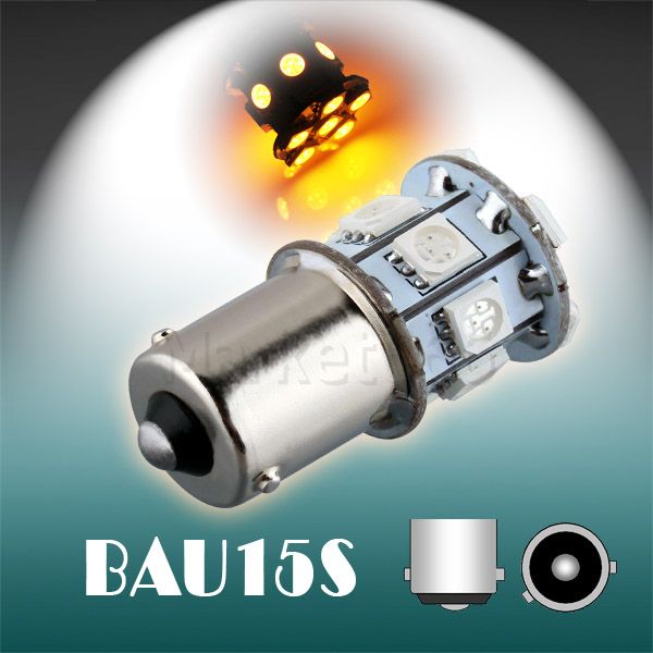
    In shortly here is the procedure how to fix fast turn signal issue with LED amber turn signal lights like this bought cheap from ebay.


    Well here is how I did it...

    You need to modify the hazard switch. So to take it apart you need to remove the metal retaining clips either side. Once these are removed you can begin to weasel things apart. I found the best was to use a small jewelers flat blade screwdriver to hook under and unhook the metal tab from the back of the unit and slide them out. Once you've done this, you can get a screwdriver in the back of the unit to unhook the plastic lugs that the metal clips hooked into. Then just pull the red hazard button off.


    My car is A6 C5 preface lifted Euro model 97-00 so turn signal hazard switch look like this (part number 4B0941509) the same or similar are also on A4
    It is preety basic mechanical switch with bimetal


    The facelifted model 01-0X has different switch and this flasher is electronic, and features two independent relays to toggle to current out to the four corners. It also is responsible for the 4-way hazard lighting as well.and look from inside like this:


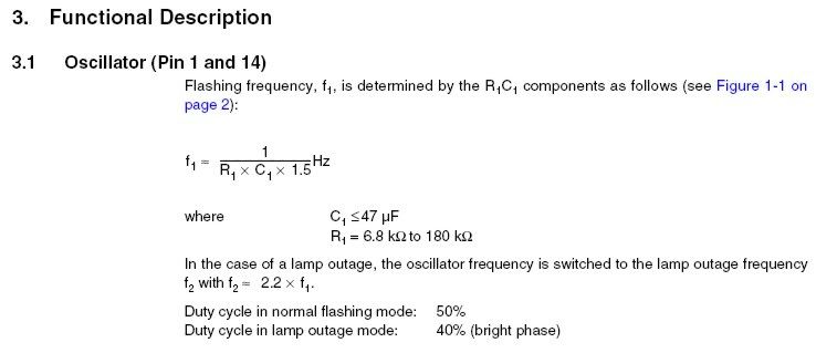
    Here are some basic formulas you need, but you wont, cause I will tell you what to do:


    So with this trick you have :

    1. Clear look headlamps
    2. Energy saving
    3. No need for any resistors in headlamp so there is no wasted heat with resistors before the headlight, and everything is made directly in the relay.
    4. Currently switching on / off
    5. No fast flash

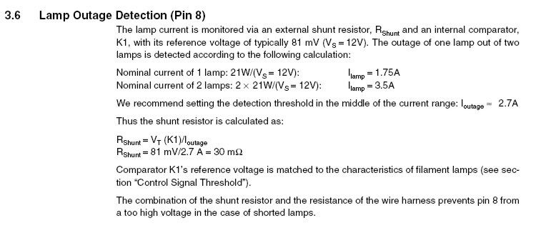
    What we need to mod is so called SHUNT RESISTOR which is special wire and found that the R(shunt) resistance is what actually measures the loads for the bulbs, and the threshold set by this value will determine at what point the unit will invoke the hyperflashing. On the board itself, the shunt resistance is provided by this item: ( U SHAPED METAL)

    FOR PREFACELIFTED


    FOR FACELIFTED MODEL look at few pictures above

    I know, it doesn't look like your 'typical resistor', but the length of it in addition to the wiring harness plays a role....go figure.....

    Nonetheless, what I am trying to achieve is to modify the load sense circuitry so that rather than expecting l(lamp) being an average of 2.7A for filament bulbs, is to 'tune it' so that it now is looking for 800-900mA loads as the norm (VLEDS list the CK switchback at ~ 450 mA, the 7443 is in the same neighborhood).

    At the end of the day (and some math), the shunt resistor would now need to be tuned to a value of 0.1-0.1 Ohms rated for at least 1 watt. This would result in normal flash rates for the following scenarios:

    [2] regular filament bulbs running - if one filament fails, no hyperflash. If both fail, then hyperflash
    [1] LED and [1] filament bulb running - if LED fails, no hyperflash. If filament fails, then hyperflash
    [2] LED bulbs running - if one or both LEDs fails, then the unit will invoke hyperflash


    SO WHAT YOU ONLY NEED IS TO BUY 0.1 Ohm resistor at least 2 W or more

    Here is how mine look it is prety bulky so I need to take of the ceramic coat to fit into the standard case of hazard switch relay


    So next step i did is that I cut the top of U shaped shunt resistor and to soldier wire that 0.1 OHM resistor to get more load.

    Excuse the crappy soldering job, but I was in a hurry


    Anyway, the key here is to remember that the length of the resistor leads will have an effect on the resistance values seeing as we are dealing with such small tolerances.
    The IC chip is very well rated, and will not be harmed by something warm touching it - currents at the board level are so small, that heat dissipation will not be any concern or problem.
    The relay goes back into the harness as per normal and you are done!


    Testing:

    So I tested and found that the relay now operates with 2 filament bulbs at exactly the OEM blink rate. Same audible click we have all grown to love. One LED in the rear and filament in the front produces the same result. Two LEDs is also consistent.
    Removal of one of the LED bulbs is confirmed to invoke hyperflashing to alert you that one of the LEDs has failed. The modded relay does not generate any tangible heat, and functions normally for both turn signal functions as well as Hazard warning lights.


    I hope you find this write-up helpful! Remember - this information is for information only, and any warranty/liability blah blah blah entirely up to you
    I plan to source out locally a proper single resistor and replace my test ones later on down the road.

    Will update with few pictures how they work

    Cheers and enjoy!

    Bruno

  2. #2
    Junior Member One Ring brun's Avatar
    Join Date
    Jan 04 2013
    AZ Member #
    106828
    My Garage
    Audi a3 8p, Allroad C6 V8 4.2 , Citroen DS21 '74
    Location
    Croatia


  3. #3
    Established Member Two Rings
    Join Date
    Jul 20 2009
    AZ Member #
    45230
    Location
    FRANCE

    I did it in a slightly different way because with your mod, some led bulbs will not work (as the Cree 1156/1157 bulbs
    with DC/DC converter inside, infinite resistance b/w the 2 poles)
    The shunt mod is not enough.
    A typical 1156 Cree bulb draws 600mA @12V, once swithed on.


    The way Audi did it in term of electronic schematic, once you act the turn signal lever (left or right), the original 21W bulb is supposed to tie the flasher to ground (pin 3 in the flasher connector).
    You need to draw 1W min from the pin 3 to trigger the flasher and to have the led bulbs blinking.
    I'm surprised your mod worked in your case b/c you have the U2043B and this one requires 10W on pin 8 to start-up. (10W/12V = 833mA !)
    In my case, it's U6043B and this one requires only 1W on pin 8, and OEM shunt is 18mOhms instead of 30.
    Threshold voltage is also a bit different (for hyperflashing), 49mV in my case, 90mV in yours.


    So, personnally, I replaced the shunt with 33mOhms / 2W and added two 220 Ohms resistors / 2W b/w the pins 5 and 7 and pin 9 (GND) of the flasher which are the pins that connect directly to the bulbs (L & R).
    With this mod, the positive pole of the bulb is tied to ground and that triggers the flasher when you act the lever.
    Last edited by RC200; 03-25-2019 at 01:39 AM.

  4. #4
    Active Member One Ring
    Join Date
    Oct 31 2013
    AZ Member #
    127876
    Location
    Seattle

    Would this work on a 06 A6?

    Or does any one know what color turn signal wire to add a resister?

  5. #5
    Established Member Two Rings
    Join Date
    Jul 20 2009
    AZ Member #
    45230
    Location
    FRANCE

    the flasher is probably the same, remove it and post/check the pics.
    Audi doesn't change something that works.
    Check the flasher connector, pins numbering is stamped inside

  6. #6
    Senior Member Three Rings Jimmy G.'s Avatar
    Join Date
    Nov 08 2010
    AZ Member #
    66738
    My Garage
    Metrocard
    Location
    The Brook

    Would the same effect be achieved by purchasing CANBUS LED bulbs?
    Audrey the Audi

  7. #7
    Veteran Member Four Rings V1nny's Avatar
    Join Date
    Dec 04 2012
    AZ Member #
    105252
    Location
    Arlington VA

    Quote Originally Posted by Jimmy G. View Post
    Would the same effect be achieved by purchasing CANBUS LED bulbs?
    There is really no such thing as "CANBUS LED bulbs". It is a confusing (intentionally so?) term, invented by the sellers of LED with built in resistors. Unlike low power resistors inside the hazard switch, these are high power resistors designed to convert large portion of power into heat, simulating the load of the incandescent bulb. It defeats the purpose of upgrading to LED's.

  8. #8
    Established Member Two Rings
    Join Date
    Jan 18 2010
    AZ Member #
    53559
    Location
    Spokane Washington

    I hate to revive an old thread, very old again sorry. But does anyone have any pictures of this??? Id like to go this route instead of the resistor route. Just changed every bulb in my c5 to LED and the hyper flashing of the turn signals is getting to me lol. Love all my extremely bright lights though!!!

  9. #9
    Established Member Two Rings
    Join Date
    Jul 20 2009
    AZ Member #
    45230
    Location
    FRANCE


  10. #10
    Registered Member One Ring
    Join Date
    Jan 22 2018
    AZ Member #
    412857
    Location
    Warrington UK

    Quote Originally Posted by RC200 View Post
    I did it in a slightly different way because with your mod, some led bulbs will not work (as the Cree 1156/1157 bulbs
    with DC/DC converter inside, infinite resistance b/w the 2 poles)
    The shunt mod is not enough.
    A typical 1156 Cree bulb draws 600mA @12V, once swithed on.


    The way Audi did it in term of electronic schematic, once you act the turn signal lever (left or right), the original 21W bulb is supposed to tie the flasher to ground (pin 3 in the flasher connector).
    You need to draw 1W min from the pin 3 to trigger the flasher and to have the led bulbs blinking.
    I'm surprised your mod worked in your case b/c you have the U2043B and this one requires 10W on pin 8 to start-up. (10W/12V = 833mA !)
    In my case, it's U6043B and this one requires only 1W on pin 8, and OEM shunt is 18mOhms instead of 30.
    Threshold voltage is also a bit different (for hyperflashing), 49mV in my case, 90mV in yours.


    So, personnally, I replaced the shunt with 0.33 Ohms / 2W and added two 220 Ohms resistors / 2W b/w the pins 5 and 7 and pin 9 (GND) of the flasher which are the pins that connect directly to the bulbs (L & R).
    With this mod, the positive pole of the bulb is tied to ground and that triggers the flasher when you act the lever.
    I've been following this thread with some deal of interest as the 6043B IC is used in the relay for my Audi A2. I've successfully modified the shunt resistor to a 0.33 Ohm 5W resistor and added in 2 x 220 1/4W resistors between pins 5, 7 & 9 and although flashing is at the correct rate, I always get a short chirp sound or buzz from the relay when the indicator is first activated. This doesn't happen when the hazards are turned on, only when using the stalk switch. If you do it 2 or three times in quick succession, the noise gets less and less loud, before actually going away.

    Is this a stalk issue (it functions well as does the cruise functions on the stalk)? There's none of the random clicks other users have noted. I'm using Osram LEDriving bulbs all round (7557YE-02B) and Osram W5W LEDriving repeaters.

  11. #11
    Established Member Two Rings
    Join Date
    Jul 20 2009
    AZ Member #
    45230
    Location
    FRANCE

    Quote Originally Posted by Skipton01 View Post
    I've been following this thread with some deal of interest as the 6043B IC is used in the relay for my Audi A2. I've successfully modified the shunt resistor to a 0.33 Ohm 5W resistor and added in 2 x 220 1/4W resistors between pins 5, 7 & 9 and although flashing is at the correct rate, I always get a short chirp sound or buzz from the relay when the indicator is first activated. This doesn't happen when the hazards are turned on, only when using the stalk switch. If you do it 2 or three times in quick succession, the noise gets less and less loud, before actually going away.

    Is this a stalk issue (it functions well as does the cruise functions on the stalk)? There's none of the random clicks other users have noted. I'm using Osram LEDriving bulbs all round (7557YE-02B) and Osram W5W LEDriving repeaters.
    Seems you performed no calculation at all. You're at the boundaries somewhere.
    Tell me how much current draws each bulb.

  12. #12
    Registered Member One Ring
    Join Date
    Jan 22 2018
    AZ Member #
    412857
    Location
    Warrington UK

    The PW21Y LEDs draw 135mA each and the little repeaters draw 55mA. 325mA per side, plus whatever the dashboard light draws.

  13. #13
    Registered Member One Ring
    Join Date
    Jan 22 2018
    AZ Member #
    412857
    Location
    Warrington UK

    I'm guessing that the shunt resistor should be more in the region of 0.2ohm (49mV/235mA) for the 6043B IC? The 220R connected to pins 5,7,9 are still fine though.

  14. #14
    Established Member Two Rings
    Join Date
    Jul 20 2009
    AZ Member #
    45230
    Location
    FRANCE

    I'm puzzled with the shunt value I really put. I forgot.
    33mOhms means I draw at least 1.5A per side in working order ... anything below would trig the hyperflashing.
    I use 1157 cree led bulbs.

    Anything in the region of 0.2 Ohms should be ok for you, 135mA per bulb is quite low for repeaters, even using leds.
    If the problem persists, have a look to pin 8, R2 and starting condition.


    1/4W for the 220 Ohms resistors is not enough @14V, you are in the 1W region.


    http://www.mouser.com/ds/2/36/doc4726-29542.pdf
    Last edited by RC200; 03-25-2019 at 01:41 AM.

  15. #15
    Registered Member One Ring
    Join Date
    Jan 22 2018
    AZ Member #
    412857
    Location
    Warrington UK

    The shunt value is derived from the reference voltage in the 6043 IC (49mV) divided by the current draw of the lamps in circuit, well, a little less than the lamps actually. In my instance, the current of one lamp would be 135mA, two lamps would be 270mA and with the repeater, 325mA. As per the Mouser 6043B reference document, I've chosen 235mA as a cut-off value, so 49/235 gives 0.209 ohms.

    I'm a little unsure of the way you derive the resistances between pins 5, 7 and 9 though. The Mouser document only mentions the 1 watt needed to start and the recommend 1.5 to 2.2 k-ohm value in the schematic.

  16. #16
    Established Member Two Rings
    Join Date
    Jul 20 2009
    AZ Member #
    45230
    Location
    FRANCE

    220 ohms: i think I did it with trial and error. I wanted the max possible value not to draw too much current, when the led bulbs start to blink correctly at 12v nominal. Basically it's less than 1w ...
    Again, 1/4watt is not enough, yours will burn and depending where you located them, it may trig 🔥. 1w is ok but 2w is safer. It must work for having blinkers on unlimited time...
    Did you solve your relay buzzing sound with 0.2 ohms shunt !?

  17. #17
    Registered Member One Ring
    Join Date
    Jan 22 2018
    AZ Member #
    412857
    Location
    Warrington UK

    I've not tried a 0.2 ohm shunt yet. I'm still puzzled by the 220R resistor derivation and how they make pin 8 draw trigger - however, I'll get some 2W 220R and try again.

  18. #18
    Established Member Two Rings
    Join Date
    Jul 20 2009
    AZ Member #
    45230
    Location
    FRANCE

    The 220 Ohm resistor (one on each side) mimic a filament bulb as led bulbs have "infinite resistance". It allows to pull more or less the 1W required from the spec. when the blinker lever is triggered.

    I'm pretty sure now your buzzing sound comes from there: 220 Ohms is too high for you b/c your led bulbs draw only 135mA. Try with 100 Ohms just for a test.
    Your flasher has difficulties to start and is oscillating.
    It doesn't buzz when you act the SOS flasher because your feed 4 bulbs at a time.

    In my case, it doesn't happen because my led bulbs draw at least 1.2A per side and the current rush is higher, making the flasher starting immediately.

    Pay attention that 100Ohms @14V means 0.14A and P=RIČ, i.e. 1.96W, you would need >3W to be safe

  19. #19
    Registered Member One Ring
    Join Date
    Jan 22 2018
    AZ Member #
    412857
    Location
    Warrington UK

    See, this is where I'm a little confused. I'm aware that due to the physical construction of a LED, there's no continuity between + and earth - as you say, it's effectively open circuit or infinite resistance. This is why CANbus fooling power resistors are typically fitted.

    The rough working (lit) resistance of a typical 21w incandescent bulb is around 9Ω, and a CANbus-defeating resistor typically fitted would be of this value. Power wise, it'd be around 25W (9 x (14/9)Č). Now I realise that these values are for resistors fitted at the bulb, not in the relay, but I'm unsure of why 220R was arrived at, even for your application of roughly 1.2A per side of LEDs. I don't like going down the trial and error route without having the theory behind it.

    The shunt resistor maths is fine - it's all explained in the 6043B schematic, but I can't see the relationship between 220Ω and 1W using 2 x 600mA LEDs

  20. #20
    Established Member Two Rings
    Join Date
    Jul 20 2009
    AZ Member #
    45230
    Location
    FRANCE

    4.7 Pin 8, Start Input
    Start condition for flashing: the voltage at pin 8 has to be below the K3 threshold (flasher switch
    closed).
    Humidity and dirt may decrease the resistance between 49 a and GND. If this leakage resistance
    is > 5 kΩ, the IC is still kept in the off-condition. In this case the voltage at pin 8 is between
    the thresholds of comparators K2 and K3.
    During the bright phase the voltage at pin 8 is above the K2 threshold, during the dark phase it is
    below the K3 threshold. For proper start conditions a minimum lamp wattage of 1W is required.

    ==> 12V/220= 0.054A

    P= RIČ= 220*0.054Č= 0.65W. There's is probably margin there, and in my case 0.65W is enough to start the flasher, but my led bulbs are 600mA each meaning they also participate to the current rush.

  21. #21
    Registered Member One Ring
    Join Date
    Jan 22 2018
    AZ Member #
    412857
    Location
    Warrington UK

    Aha - with you. So it's just that in my case, the low current draw of 325mA isn't enough to make up the wattage from 0.65w to 1w.

    I shall order in some 100Ω and 50Ω resistors, although fitting 50Ω 3w resistors to the pins will be very tight. I think 100Ω 2w will be the best solution and the one I'll end up using.

  22. #22
    Established Member Two Rings
    Join Date
    Jul 20 2009
    AZ Member #
    45230
    Location
    FRANCE

    I fitted the 220ohms close the rear taillights, there's more room there.
    You're not obliged to put the resistors close to the flasher unit

  23. #23
    Registered Member One Ring
    Join Date
    Jan 22 2018
    AZ Member #
    412857
    Location
    Warrington UK

    No, I realise that - you're just bridging pins together after all. I'm a neatness fanatic though and if I can make it all work internally inside the relay case, then I will. Doing more maths, I'm going to go for 150Ω 2W as that'll give me a power draw of 0.96W, which will tip pin 8 into action even with my low current bulbs. Thanks for your replies RC200 - you're a gent!

  24. #24

  25. #25
    Veteran Member Four Rings hoganalley's Avatar
    Join Date
    Feb 23 2007
    AZ Member #
    15868
    Location
    Burlington

    so what do we do with this switch? I want to do the same but this is a different setup than above.

    14 A4 allroad - stock
    05 allroad 2.7T Stock

  26. #26
    Established Member Two Rings
    Join Date
    Jul 20 2009
    AZ Member #
    45230
    Location
    FRANCE

    Apparently, there's a shunt on the left side. You need to fit LED bulbs and check how your flasher reacts. Then, dig into, check ICs part numbers .... Look like your flasher is old fashion (2 relays, analog stuff)

  27. #27
    Veteran Member Four Rings hoganalley's Avatar
    Join Date
    Feb 23 2007
    AZ Member #
    15868
    Location
    Burlington

    Quote Originally Posted by RC200 View Post
    Apparently, there's a shunt on the left side. You need to fit LED bulbs and check how your flasher reacts. Then, dig into, check ICs part numbers .... Look like your flasher is old fashion (2 relays, analog stuff)


    There is a shunt, yes. So I will cut the shunt and solder an appropriate sized resistor and test?

    Sent from my ONEPLUS A6003 using Audizine mobile app
    14 A4 allroad - stock
    05 allroad 2.7T Stock

  28. #28
    Veteran Member Four Rings m_haiser's Avatar
    Join Date
    Apr 24 2011
    AZ Member #
    74529
    My Garage
    2012 A6 Prestige, 1998 Jeep Cherokee XJ
    Location
    Central Willamette Valley

    what would one do if they had all regular (non led) bulbs and had hyper blink from the hazard button?

  29. #29
    Veteran Member Four Rings hoganalley's Avatar
    Join Date
    Feb 23 2007
    AZ Member #
    15868
    Location
    Burlington

    Quote Originally Posted by hoganalley View Post


    There is a shunt, yes. So I will cut the shunt and solder an appropriate sized resistor and test?

    Sent from my ONEPLUS A6003 using Audizine mobile app
    IC is U2043L.

    From my understanding I will be similar to RC200's post 3. My bulbs appear to be 10.5W @ 12V so 0.88A.

    What resistors would be best suited to my setup?
    14 A4 allroad - stock
    05 allroad 2.7T Stock

  30. #30
    Veteran Member Four Rings hoganalley's Avatar
    Join Date
    Feb 23 2007
    AZ Member #
    15868
    Location
    Burlington

    Alright, I'm back on this because I want to get this done.

    Here is my math for what my setup will be:

    Front Turn Signal Bulbs: 12V @ 3.6W = 0.3A
    Side Markers: 12V @ 2W = 0.167A
    Rear Turn Signal Bulbs: 12V @ 3.6W = 0.3A

    Therefore, 0.3*2 + 0.3*2 + 0.167*2 = 1.53A
    Reducing this value by 1/2 of the side marker amperage brings me down to 1.363 A.

    At this point, this will trigger the hyperflash if one of my LED's goes out.

    Now, to calculate the resistor, I get this based on my switch: 0.081mV/1.363A = 0.0594 Ohms. The wattage rating of this resistor, I calculate to be 12V/0.0594 = 203.3mA, then, 12*.2033A = 2.44 W.

    So, I figure i need a 0.6 Ohm 3W resistor to handle the LED's.

    Does this seem correct? Now, how to calculate the value for the flasher resistors? on my circuit I need 10 W to create the startup surge, not 1W like the other posts.
    14 A4 allroad - stock
    05 allroad 2.7T Stock

  31. #31
    Established Member Two Rings
    Join Date
    Jul 20 2009
    AZ Member #
    45230
    Location
    FRANCE

    For hyperflashing, consider one side only: 81mV / (0.3+0.167+0.3)= 105mOhms (closest value is 100mOhms), P=RIČ i.e. 0.058W, let's take 1/8W or 1/4W to cover the case when all the corners are flashing.

    You seem to rely on the (advertised) power of your led bulbs, please measure the real current with a current meter @12V.

    For startup surge, 10W/12V=0.83A .... 18 Ohms/10W should be enough (12V/18= 0.666A), otherwise 15 Ohms/10W

  32. #32
    Veteran Member Four Rings hoganalley's Avatar
    Join Date
    Feb 23 2007
    AZ Member #
    15868
    Location
    Burlington

    Quote Originally Posted by RC200 View Post
    For hyperflashing, consider one side only: 81mV / (0.3+0.167+0.3)= 105mOhms (closest value is 100mOhms), P=RIČ i.e. 0.058W, let's take 1/8W or 1/4W to cover the case when all the corners are flashing.

    You seem to rely on the (advertised) power of your led bulbs, please measure the real current with a current meter @12V.

    For startup surge, 10W/12V=0.83A .... 18 Ohms/10W should be enough (12V/18= 0.666A), otherwise 15 Ohms/10W
    Thanks for this. I will check my bulbs with 12V. Doing research, it appears that an 18 Ohm/10W resistor is gigantic and will not fit into the hazard switch relay. I will continue looking but I don't think this will work!
    14 A4 allroad - stock
    05 allroad 2.7T Stock

  33. #33
    Established Member Two Rings
    Join Date
    Jul 20 2009
    AZ Member #
    45230
    Location
    FRANCE

    I repeat it: the resistors for startup don't need to be located in the flasher, they can be fitted close to the taillights where more space is available.

  34. #34
    Veteran Member Four Rings hoganalley's Avatar
    Join Date
    Feb 23 2007
    AZ Member #
    15868
    Location
    Burlington

    Quote Originally Posted by RC200 View Post
    I repeat it: the resistors for startup don't need to be located in the flasher, they can be fitted close to the taillights where more space is available.
    Yes, I know; I was trying to avoid having any other modifications outside of the hazard switch. Not a big deal but it would be nice to keep it all contained in the switch.

    Sent from my ONEPLUS A6003 using Audizine mobile app
    14 A4 allroad - stock
    05 allroad 2.7T Stock

  35. #35
    Registered Member One Ring
    Join Date
    Jul 08 2019
    AZ Member #
    499465
    Location
    Vancouver, BC, Canada

    Thank you very much for this thread. I want to do this for my car so I can have LED signals all around. Assuming I have the 6043B IC (haven't checked, but when I do I will revise calcs if needed), my front/rear LEDs draw 0.19A each, and I'm not sure about my repeater LEDs but they should be negligible. I've done the math like this:

    For shunt resistor:

    0.19A x 2 = 0.38A

    midpoint = 0.29A

    49mV / 0.29A = 169 mOhms

    P=RI2: 0.014W x 2 = 0.028W

    Therefore shunt should be 169 mOhm 30mW (can't seem to find less than 1W, I assume higher W doesn't matter).

    For startup surge:

    1W/12V=0.083A

    144 Ohms 1W resistor

    I don't understand this bit, at 12V 0.38A the watts should be 4.56W, and therefore I don't need any startup surge resistors as it is more than 1W. But, I don't know how many volts my LEDs need, they are rated 10-30V, but I have to assume they need less than 10V or nobody would require startup surge resistors. Is that right? If that's the case I'm not sure what resistors I should be using - 150 Ohms 2W seems like it would be a safe choice?
    Last edited by Slikk; 07-08-2019 at 03:33 PM.

  36. #36
    Established Member Two Rings
    Join Date
    Jul 20 2009
    AZ Member #
    45230
    Location
    FRANCE

    DC-DC LEDs are not a resistive load, so ... need resistor.
    150ohms/1W may be enough as repeaters blink only, check heat dissipated in warm weather.

  37. #37
    Established Member Two Rings
    Join Date
    Jul 20 2009
    AZ Member #
    45230
    Location
    FRANCE

    Btw, 0.29A is a bit on the low side for repeaters. I have 500-600mA each.

  38. #38
    Registered Member One Ring
    Join Date
    Jul 08 2019
    AZ Member #
    499465
    Location
    Vancouver, BC, Canada

    Quote Originally Posted by RC200 View Post
    150ohms/1W may be enough as repeaters blink only, check heat dissipated in warm weather.
    Not sure what you mean (assuming front/rear signals used as running lights?), on my car all signals are blink only. My repeaters are 15 diodes each, but I have no idea on current as they do not say on the website and I haven't received them yet.

    0.29A is only for 1 front + 1 rear signal at 0.19A each, I was not counting the repeaters as I assumed the current draw for them would be low and not affect it that much. In any case it looks like the only resistor I can find in stock is 180mOhms 1W for the shunt, so the threshold will be more like 0.27A. You are thinking 1 repeater + 1 signal will be more than 0.27A and thus not trigger hyperflash if a signal goes out? Tbh I'm not sure I care if it doesn't hyperflash if a signal is dead, I will likely notice it anyways.
    Last edited by Slikk; 07-08-2019 at 03:35 PM.

  39. #39
    Registered Member One Ring
    Join Date
    Jul 08 2019
    AZ Member #
    499465
    Location
    Vancouver, BC, Canada

    Tried to get my hazard switch apart, unfortunately it appears to be designed in such a manner that the circuit board is captive once it is assembled (6 pins are soldered on that hold it permanently in place, thanks to the design of the housing). I can't get at the circuit board itself without entirely disassembling the switch, so I'm pretty much dead in the water.

    If I'm feeling destructive later I might attempt to desolder the pins, but as I don't have much experience desoldering anything, I probably won't bother. Looks like I'm falling back on hacking up the wiring harness to wire in a standalone relay.

  40. #40
    Active Member One Ring
    Join Date
    May 30 2019
    AZ Member #
    488081
    Location
    chicago

    This led tutorial is a decade ago. Is there any new tutorial like 2019?

Bookmarks

Posting Permissions

  • You may not post new threads
  • You may not post replies
  • You may not post attachments
  • You may not edit your posts
  •  


    © 2001-2025 Audizine, Audizine.com, and Driverzines.com
    Audizine is an independently owned and operated automotive enthusiast community and news website.
    Audi and the Audi logo(s) are copyright/trademark Audi AG. Audizine is not endorsed by or affiliated with Audi AG.