


I just installed the Magnaflow 16586 exhaust system (2.5" catback with x-pipe and resonators) on my 2004 S4 (LOVE it, by the way), and decided to gut my pre-cats while I was at it. I'll leave the miserable broken manifold stud story for another post...
So anyway, with the pre-cats gutted, you'll obviously throw a CEL, and I have found a fix that works great for me. I've been roughly 250 miles, with about 20 start/stop cycles, and no codes :-)
I was hesitant to use the spark plug defoulers, as I've heard of about 50% success rate. I did some preliminary reading on a diode modification where the diode is in series with the signal wire, and it sounded good so I tried it. That doesn't work either, as it often doesn't have enough voltage to turn on, and creates an open circuit... My mod uses a shunt diode/resistor combination, which is where it differs from the series diode in the other mod.
Here is my solution, which works for me, and I give no guarantees, but the electrical principals show no reason why it shouldn't work across the board.
NOTE: This modification is easily performed under the hood on the green and brown O2 sensor plugs. Locate the plugs at the firewall, and make sure you are modifying the wiring on the O2 sensor side, not the ECU side. This allows you to easily revert back to stock if necessary. I used solder connections for the black wire, and a crimp (with shrink wrap) on the grey wire, because it would not take solder...
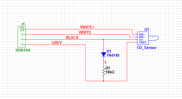
This schematic shows my solution, using a 1N4148 axial-lead diode, and a 10k 1/8W axial-lead resistor.
The explanation:
Voltage from the (+) terminal of the O2 sensor ranges from 0.2V-1.2V. The acceptable range (from what I've read) is 0.2V-0.8V. The 1N4148 diode has a turn-on voltage of roughly 0.3V. This is when the diode begins to conduct, and it conducts more as the voltage increases, until around 0.7V where it acts like a short.
When the voltage on the (+) terminal (black wire) of the O2 sensor reaches 0.3V or higher, the diode begins to conduct, and redirects some current (and voltage) through the 10k resistor to ground (grey wire). It does this at an increasing rate as the voltage increases, until it reaches maximum conductivity, around 0.7V. In simulation, this circuit does not allow the voltage at the (+) terminal (black) to be any higher than roughly 0.7V (when the O2 is trying to put out 1.2V).
This means that the voltage varies as it needs to, never reaches zero, and never goes over an allowable 0.7V. Also, there is a direct path from the ECU to either pin on the sensor, if it needs to access it for impedance measuring.
Let me know if this works for you, I hope it does!!

 Reply With Quote


 ) 2005.5 Audi S4
 2011 Dieselgate Q7 TDI..... patiently waiting for my warranty to expire!!


Bookmarks