


Materials needed :
16 or 18 guage wire
2 DEI 528 T pulse timer
5 SPDT relays
Digital multimeter
phillips screwdriver
8mm racthet
zip ties
I missed anything I be sure to mention it below
So I have to apologize because I can't seem to find all of the pics I took but for the most part you don't need most of them.
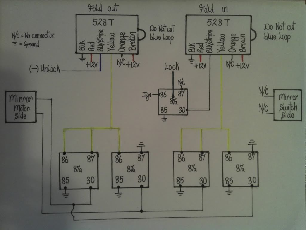
This is the wiring diagram of how the mirrors connect to the DEI 528 T pulse timer & the spdt relays and I would suggest wiring these up before going out to the car.
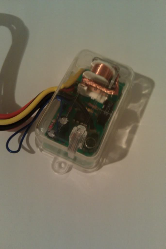
This is a pic of the DEI 528 T pulse timer, I purchased mine on ebay for about $13 each.
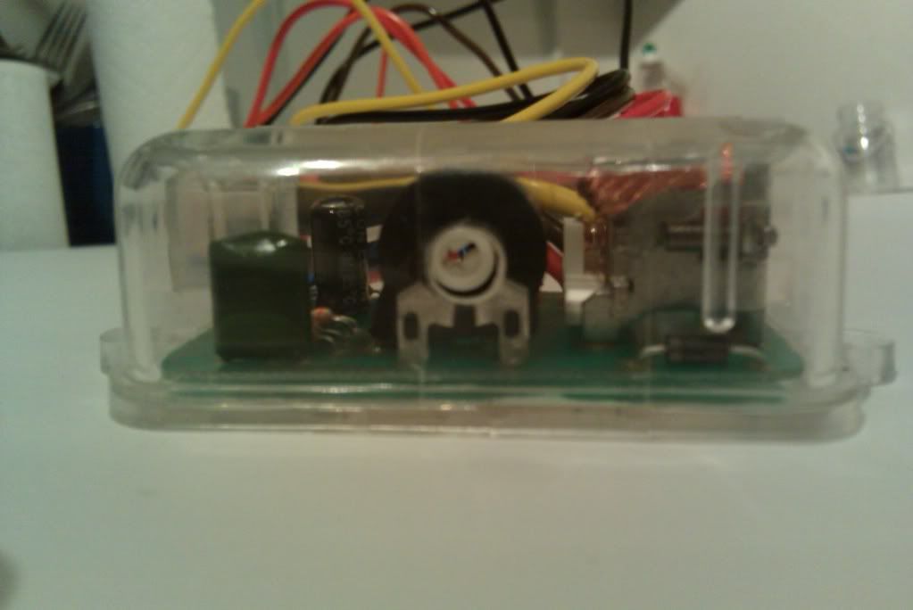
This pic shows the adjustment knob which needs to be adjusted to about 3.5 sec, this timer can adjust between 0-60 sec so it doesn't need to go to far.
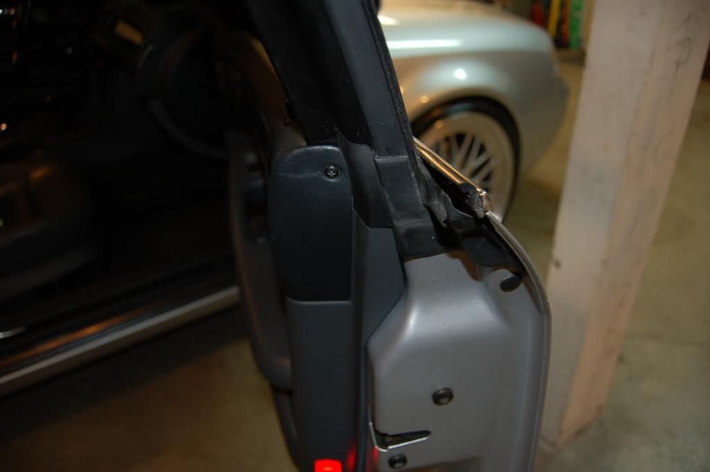
So to start you'll need to remove your driver side & passenger side door panels. This is easy as there are only two phillips screws at the top of the door panel to be removed at least on my 04. I only took it off enougn to reach the wires needed. I can't find my pics of this so I stole the ones from Dre's door led thread, sorry Dre.
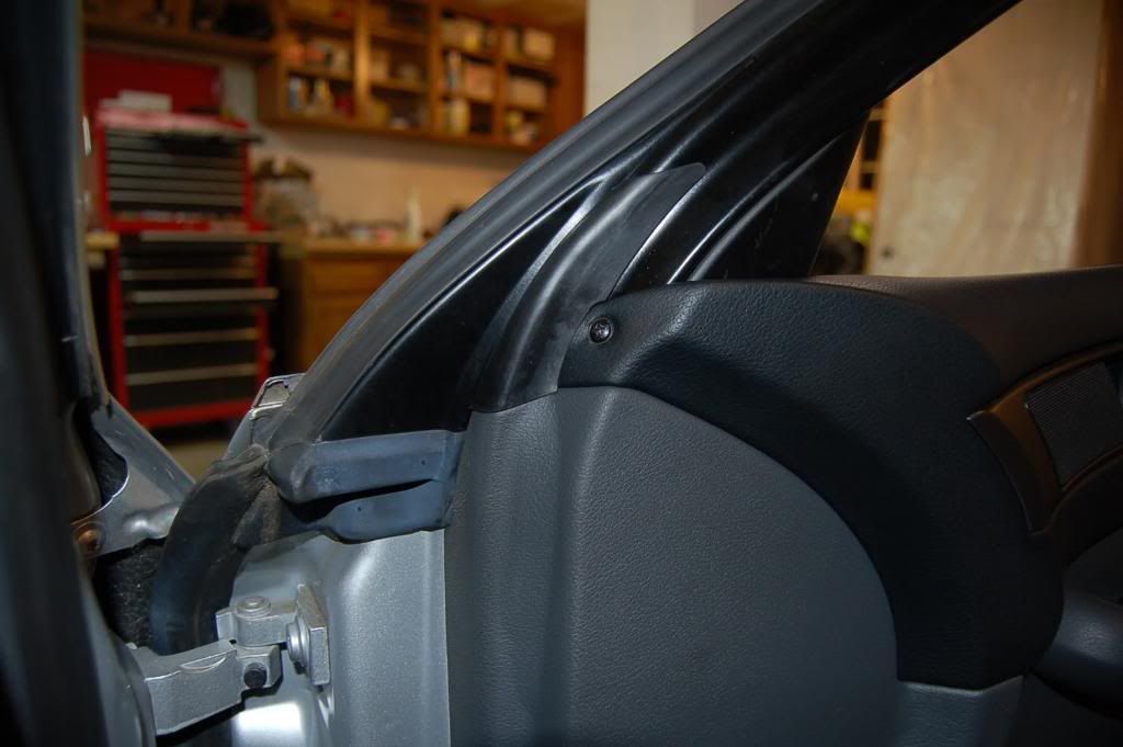
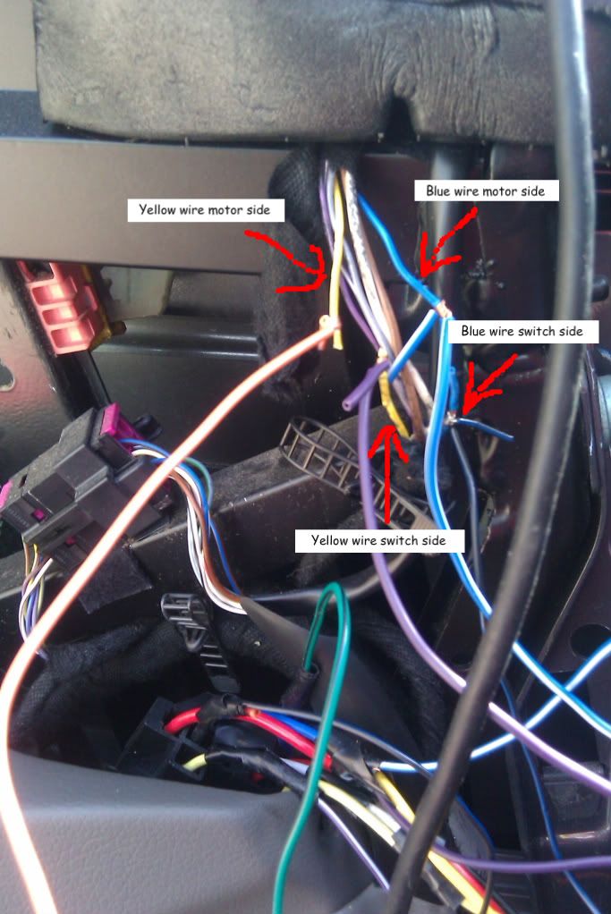
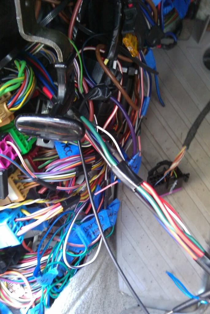
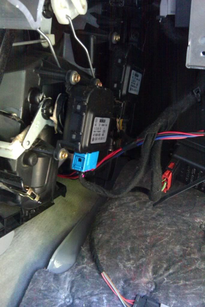
So once the door panels are off you need to located the two wires that power the mirrors, now on my 04 s-line these two wires are blue and yellow, you can see them here.
Now for those of you attempting this on a different model or year as long as you test and find the two wires that power the mirrors everything else beside those two wire colors will be the same. Now to explain a little further the two wires will be reverse polarity which basically means that one wire sends power while the other sends ground to move the mirrors, then the wire that sent power before will now send ground and vice versa for the other wire. So if the blue gets power & the yellow gets ground to fold out the mirrors, the blue wire will get ground & the yellow wire will get power to fold them in. To test this, if your wire colors are the same as mine should make it easy, if not it might just take you a little longer. I used a power probe for testing but you can use a digital multimeter set to vdc ground the black wire put the red one on the suspected wire, now obviously the wire should be striped alittle to expose the wire itself. Turn the car to the on position and turn your mirror switch to see what the wires do. Now when you find the right wires you want to write down which wire does what so it can be match up to the wiring diagram above. So the wire that has power on fold out will be wired to pin 30 of the 1st relay on the bottom left and the the wire that gets ground on fold out will be wired to the 2nd relay from the bottom left. Pin 30 of the 3rd relay from the left will be wired to pin 30 of the 2nd relay from the left and pin 30 of the 4th relay from the left will be wired to pin 30 of the 1st relay from the left. If you have an aftermarket alarm on your car it will make wiring the lock an unlock much easier those wires are usually blue & green and paired together in a 2 pin harness from the alarm brain, so if you do just tap in to those. If you want to do this with your factory remote you'll have to find your factory lock & unlock wires which is located @ the central locking control module which isunder the carpet in front of the drivers seat. The lock wire is green/blue pin 12 & the unlock wire is brown/yellow pin 6(sorry no pics).
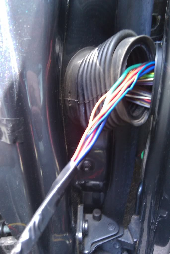
So after you locate the two wires that power the mirrors cut them and tape off the side going back to the switch, attach new wire to the motor side, now make sure to write down which one is which especially if they're not using the same color wire. I soldered mine but you can use what ever method you like. Run the wires through the rubber boot in each door.
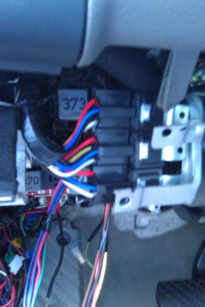
You'll have to remove your drivers side kick panel held in place by 5 8mm bolts, you have to remove the plastic piece right in front the lcd display to access the 2 top bolts on the bottom you'll see the other 2 through access holes on either side of the panel, the fifth on you have to access through the fuse panel(sorry no pics). You also need to remove the panel to the left of the dead pedal or foot rest whatever that thing is called held in place by 2 phillips screws. On the passenger side you have to remove the glove box which is held in place by 5 8mm bolts.
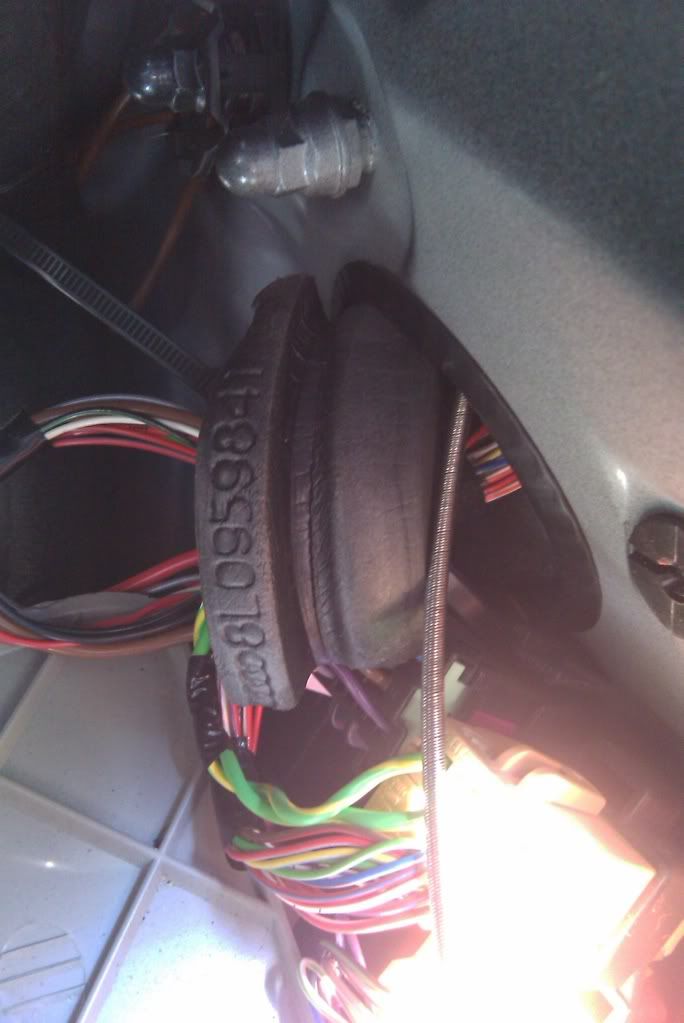
Here is my little metal snake entering the drivers side, the foam piece can be removed for better access.
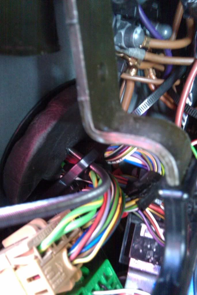
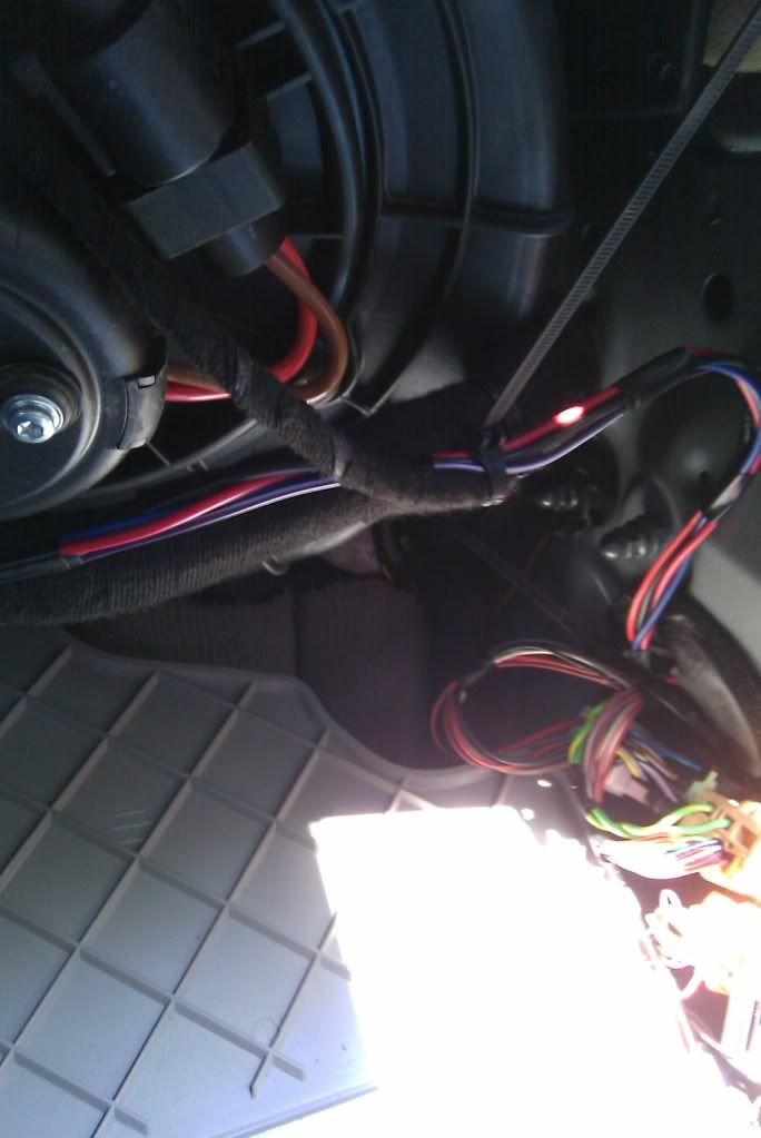
Here it is on the passenger side
I ran the wires from the passenger side mirror, pass the blower through a little open area above the transmission hump
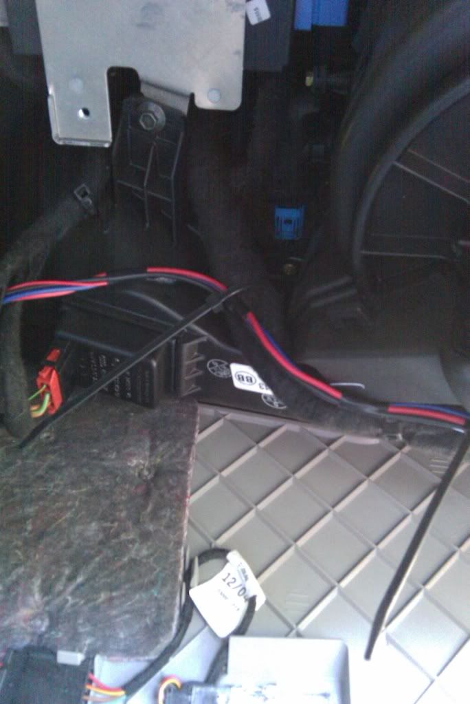
I ran all my wires to the drivers side that is where I put my timers & relays, there's a good spot here
So once you have everything wired up this should be the results
http://s305.photobucket.com/albums/n...=VIDEO0020.mp4
I'm sure I probably missed a few things so PM me with any questions.


Bookmarks