


I have noticed that lately there have been numerous threads concerning the mess of vacuum hoses and check valves present on the 1.8T motor. A particularly good thread worth reading is this one (Clicky click ). I am glad to see that many are taking the approach of maintaining the systems rather than just ripping everything out. Usually when you do this there are some adverse effects (such as unwanted CEL’s and failed emissions testing). The exact configurations of these systems vary from year to year so instead of trying to identify each component I thought it might be a little more useful to describe what each system does so the function can be applied to whatever system is on your particular model year.
Keep in mind that all of these systems are vacuum operated. The vacuum sources can either be the TIP (turbo inlet pipe) or the intake manifold. On a normally aspirated motor the intake manifold provides a constant source of vacuum. However, with a turbo the intake manifold switches from vacuum to boost pressure. Consequently any and all vacuum line connected to the intake manifold will have to be protected by a check valve. The check valve will always allow flow toward the intake manifold and will block the boost pressure from going in the opposite direction.
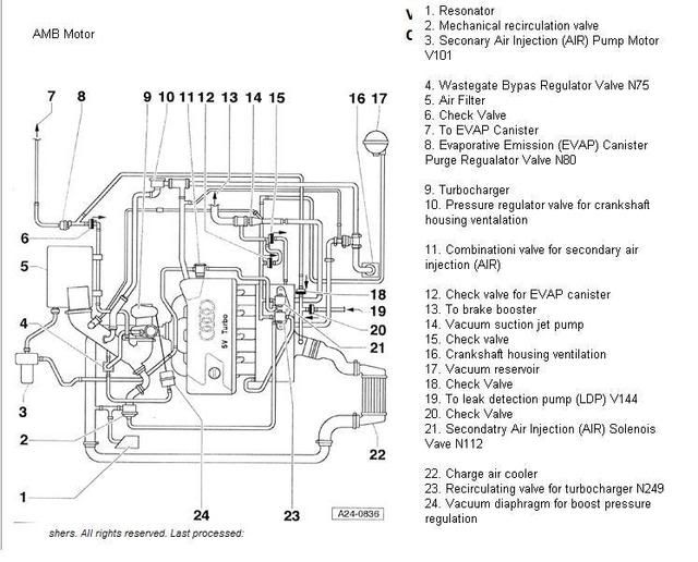
There are basically 5 separate systems. The evap emissions control (N80), block breathing (PRV/PCV), brake vacuum (suction jet pump), DV modulation (N249) and SAI (N112) system. Depending upon the model year various components of these systems may be cross connected but the basic function remains the same. Only 2 of these systems actually move air. That would be the emission control and block breathing systems. The other 3 systems simply provide a vacuum source.
Evap emissions control: This system provides the purging and burning of the hydrocarbons that collect in the fuel tank/charcoal canister. There is a collection line coming from the fuel tank canister and connecting to the N80 valve just above the air box. The fumes are pulled through the N80 valve and ultimately into the intake stream. Just past the N80 valve there is a “Y” connector that provides the necessary vacuum source. One line from the “Y” runs across the back of the motor and ultimately connects to the intake manifold. This line is protected with several check valves for when the manifold is under boost pressure. Also connected to this line is the vacuum source line for the LDP (leak detection pump) that is located in the driver’s side rear wheel well. This is one of the two hard plastic lines that you see running from underneath the intake manifold to the driver’s side front fender. The other line from the “Y” connects to the TIP to provide a vacuum source for when the intake manifold line is under boost.
Block Breathing System: The two main components of this system are the PRV (pressure regulating valve) and the PCV (positive crankcase ventilation valve) AKA the block breather valve. There are variations on the block breather and variations on the location of the PRV but the functions remain the same. When the manifold is under vacuum the purge air is pulled from the block from two different locations. One source is from the lower vent just above the oil cooler/oil filter housing. The other location is to the back of the valve cover. These two breathers are connected by fairly large diameter hoses. The two connect at a "T" located underneath the manifold. This allows the pressures to equalize between the block and valve cover. The block breather valve is inserted into the "T" and then connects directly to the intake manifold. On late 2003 and newer models there is also the small hard pipe that attaches to the larger hard pipe on the back of the valve cover. The large hard pipe on the back of the valve cover is a double walled pipe that provides a small baffle for the connection of the smaller breather pipe. This hose is is protected with a check valve and also provides additional purgeflow to the intake manifold. On '04 and newer models the check valve for this breather line is incorporated into the PCV valve as one unit.
When the block breather is pulling air out of the block the PRV is metering air into the block. This purge air is being drawn from the connection between the PRV and the TIP (turbo inlet pipe). Once the intake manifold goes into a boost condition the block breather (PCV) can no longer provide a vacuum source to purge the block pressure. As the block pressure starts to build from valve guide/piston blow-by gasses the PRV switches functions and instead of metering air into the block through a small orifice it acts as a relief valve and dumps the blow-by gasses into the TIP. There is a spring loaded diaphragm in the PRV that opens up when the block pressure builds to a high enough level.
Brake vacuum (suction jet pump): This device provides a vacuum source for the brake vacuum booster. The SJP has two internal “flapper” or check valves to provide one directional flow. The right side the the SJP connects directly to the intake manifold. The internal flapper valve prevents back-flow from when the manifold is under boost. The angled line coming from the side connects to the a hard pipe that goes behind the block and ultimately connects to the TIP. When the manifold is providing a vacuum source this flow of air through the lower section of the SJP creates a venturi effect and amplifies the vacuum pull on the upper section of the SJP. There are variations on this connection. If you have an early ('02) model you may not have the TIP connection. Instead the venturi effect is generated by running the block breather hose through the SJP. There is also the "h" shaped hose that attaches the SJP to the brake vacuum booster. It has 2 additional connections. One connection is directly to the manifold, protected by a check valve. The second connection starts at the side port of the three-way check valve and is ultimately connected to the vacuum canister located underneath the driver’s side front fender. It is used by the N249 and the N112 as outlined below.
DV modulation (N249) and SAI (N112) system: I am grouping these two systems together since they both draw vacuum from the same source. The line leaving the side port of the three way check valve referred to in the SJP section has its own check valve that provides an uninterrupted vacuum connection to the N249, N112 and the vacuum canister. This arraignment can provide a vacuum source via the vacuum canister to the N249 when the manifold is under boost. It can also provide a vacuum signal on a cold start to operate the N112. The N249 has three connections. It has a vacuum/boost signal line connection from the intake manifold, through the N249 and ultimately ending at the DV (diverter valve). The N249 also has the vacuum line referred to above. The ECU utilizes the N249 to replace the boost signal with a vacuum signal under certain conditions. The N112 is a simple on/off vacuum switch. It provides a vacuum signal to open the combi valve under cold start conditions.
I hope my ramblings will be of some aid when trying to sort out and troubleshoot the plethora of vacuum lines and check valves on out 1.8T motors. As I stated at the start there are variations on all of these connections depending upon your model year. However the basic functions all remain the same. So if you understand the function you can figure out how it goes together.
Cheers!

 Reply With Quote


 His: 2012 Moonlight Blue Metallic S5 Prestige
 Hers: 2014 Lava Gray Metallic Q5 2.0T
 Son's: 2005.5 Imola Yellow B7 S4 4.2 Sedan


Bookmarks