


Sorry in advance for the long post.
Parts:
- One of those $3.23 generic iPhone cradles from china that are sold on eBay. The kind that look like they are sturdy metal but are in actuality all bunch of plastic.
- 5 feet of 16-connector Ribbon Cable (Altex.com: RC16). You really only need 4 feet, but I found the extra foot to be helpful when running the wire. In the end, I cut it down to 4 feet.
- 4 16-pin connectors that look like the kind on an old hard-drive cable. You really only need 2, but I got a couple extra to help with the soldering process and they were pretty cheap). Altex.com IDS16 OR FCI Part# 71600-616LF. If you are clever and know how to google, you can order yourself a few samples of these.
- 2 16-pin matching shrouds for the connectors. FCI Part # 75869-103LF. As above, if you are clever and know how to google, you can order yourself a few samples of these.
- An Audi AMI-to-iPod cable you are willing to cut. I have seen these for sale on eBay for about $20. Make sure you get the same part number as the one you currently have.
- Screws and Nuts. These are going to go through the coin-slot, so they need to be long and thin. I used #4-40 x ¾ (its in a green bag with UPC 3069927461) machine screws found at my local Home Depot.
- Washers. These will be hidden when done, but will help keep the screws in place. I found some Sealing Washers #8 from Home Depot (in a white bag from a pull-out drawer with UPC 30599??228).
- 1 zip-tie strip (can be very small).
Tools:
- Soldering Iron and Solder
- Electrical Tape
- Pliers
- Scissors
- Hobby Knife (or similar)
- Screwdriver
- Black Permanent Marker (if you want)
- Drill with 3/32 and 11/64 sized bits.
- Radio removal Keys (or just pull into your local dealer and ask for a quick hand)
Instructions:
The following instructions worked for a 2010 A4 P-. If thats not you, you may have some more work on your hands.
If you do not have radio keys, you will need to go to the dealer (I went to the nearest VW dealer) and ask them to quickly pop free the AMI box inside the glove box. Do not take it completely out, just have them pull it out about 1 inch or so. The glove box will still close and everything will work fine, but you need to be able to get back behind the unit.
Take the long ribbon cable and snap on one of the connectors. Just to be sure, make sure you line up the little molded triangle on the connector with the red wire in the ribbon. Squeeze it together tightly with the pliers. With only one connector attached, bring that into the car with you, along with the other connector and the pliers. Put this aside for a moment while you remove the coin holder.
Next, we need to get that coin holder out. Pop-out the rubber boot holding the shifter and then pop-out the whole center console piece surrounding the shifter. You will see that the coin holder is held in place with a couple stiff plastic tabs-one in the front, one in the back. Try not to break a finger and pop it out. Once it is popped out, you can reassemble the console without the coin holder. Put the coin holder aside for now.
With the coin holder out and the console re-assembled, take the ribbon cable and slide the unconnected end into the coin holder, down along the passenger side. It should appear under the trim along the passenger leg area. Do not pull to far, leave about 4 inches or cable inside the coin-holder area.

Now we need to get the other half into the glove box. Fortunately, we do not have to take the whole glove box out, we just need some patience. Go back into the glove box and gently pull out the AMI box that the dealer freed. Disconnect the wire in the back and put the box to the side. If you now look in the back-upper-left corner of the glove box you will see our target. We need to take the ribbon cable and pull it stiff, and slide it up there from the bottom of the dash, again by the passengers legs. It took me about 4 tries to get it up there to be able to grab it from within the glove box.

Make sure the wire comes through the shelf area where the AMI box sits. Now, go back to the AMI box, and look for a 1 wide rectangle that pretty much sits above the little tray. We are going to run the ribbon cable through that. Pull the tray out, slide the cable in, pulling all the slack. When I did this, I found it easier to just remove the tray from the unit, but you shouldnt have to. It is now time, to put it all back together. First, hide the ribbon cable that is by the passenger legs underneath the interior trim. Feel free to fold the cable as you push it up under the trim. Second, reconnect the AMI cable that was previously attached inside the glove box. Finally, pull the tray open on the AMI box and slide it back into place. Make sure you slowly pull the ribbon cable forward as you do this. Once the AMI box snaps in place, close the little tray. Now, pull the ribbon cable and clip off any extra that goes past the end of the tray. Connect the other 16-pin connector to the ribbon cable. If you followed the suggestion above about the little triangle and the red-wire, do the exact same here. Squeeze it tight with the pliers. You are done with the glove box.
The coin holder part is not difficult at all, but just a bit of work. I can show you pictures of what I did, but a lot of this you will have to figure out as you go...
Pick up the coin holder (CH) and the cradle base (CB). You now need to decide how you want to mount the base of the CB to the CH. I chose to center it with the CB lines going forward-to-back. I then drilled small 3/32 holes for the screws to go through in the bottom of the CB. I put the screws in the base and then pressed it together with the coin holder as a temporary validation. I did NOT remove the sticky tape on the bottom of the CB. Once you start to put it together, you will see that there are some places under the CH that has to be cut. The CH has a bunch of little plastic strips on the underneath to keep coins from falling through. Those need to be cut to let the screws go through. Cut them. Once they are cut, you can make sure it will all hold nicely. At this point, I also decided to push the CB back as far as possible on the CH to make room for the wire. I then drilled a 11/64 hole in the middle of the CH for the wire to fit snugly. After the hole was drilled, I took it all apart, uncovered the sticky-tape and put it all back together, including using the washers underneath. I used a scissors to rough-cut off the overhang of the CB and then used a hobby-knife to clean it up. Now it was time for the wire-work.
First, cut the AMI-iPhone cable in half. Strip away about one inch on each side and then about 1/8 from each wire end. I also took some pliers and a wire cutter and removed the little squeeze-lock-hooks on the iPhone plug. I wanted the phone to be able to slide on and off without having to squeeze the sides.

Next, slide the iPhone plug through the top of the CB/CH.
I also took a black marker and colored the top of the screws. If I had black nail polish, I could have likely used that too.


I placed a zip-tie around the bottom of the wire, so that a strong pull (after it was complete) would not tear apart the internal wires. Cut off the end of the zip tie. Finally, I soldered.

You will be soldering the 16-pin headers to each of these. The exact placement of each color does not matter, as long as it is identical for each header. That is important, so let me repeat that... It does not matter whether the blue wire is next to the green wire once soldered as long as both headers are soldered the exact same way. I chose to put the 8 data wires on one side, the 4 power wires on the other side, and the huge ground wire in between. I will not explain how to solder, especially since I probably did a horrible job. I would recommend that you tip the wires and header with some solder before you start. You do not need much solder and this is a quick way to avoid needing three hands to solder. Another hint... take two of the extra connectors and put them into the headers while you are soldering. They will help keep the header stable and prevent too hot of a soldering iron from bending or melting the connector.


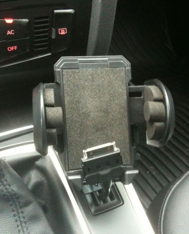
I plugged everything in and it worked. Then, I snapped it all into place. I do have one task left, which is to better secure the cable to the cradle so that I can just slide it in. I am thinking of using double-back foam tape, but that is still up in the air... Anyhow, the final product:


 Reply With Quote


Bookmarks